Cover Plate for Surface Mount Junction Box with Locking Member

Inactive Publication Date: 2009-07-16
TREMAR CORP
View PDF10 Cites 6 Cited by
  • Summary
  • Abstract
  • Description
  • Claims
  • Application Information

AI Technical Summary

Benefits of technology

[0013]Another object of this invention is to provide a novel cover plate that can be quickly and easily secured to a conventional electrical circuit device.
[0014]Another object of this invention is to provide an exceptional cover plate that can be attached to a generic electrical circuit device in a single-handed manner without the need for additional fasteners.
[0015]Another object of this invention is to provide an excellent cover plate

Problems solved by technology

Whenever an installed junction box with electrified wires fails to have a cover, this is noted as an open junction box and considered to be dangerous, since it clearly constitutes a fire or electrocution hazard.
As

Method used


Image

  • Cover Plate for Surface Mount Junction Box with Locking Member
  • Cover Plate for Surface Mount Junction Box with Locking Member
  • Cover Plate for Surface Mount Junction Box with Locking Member

Examples


Embodiment Construction

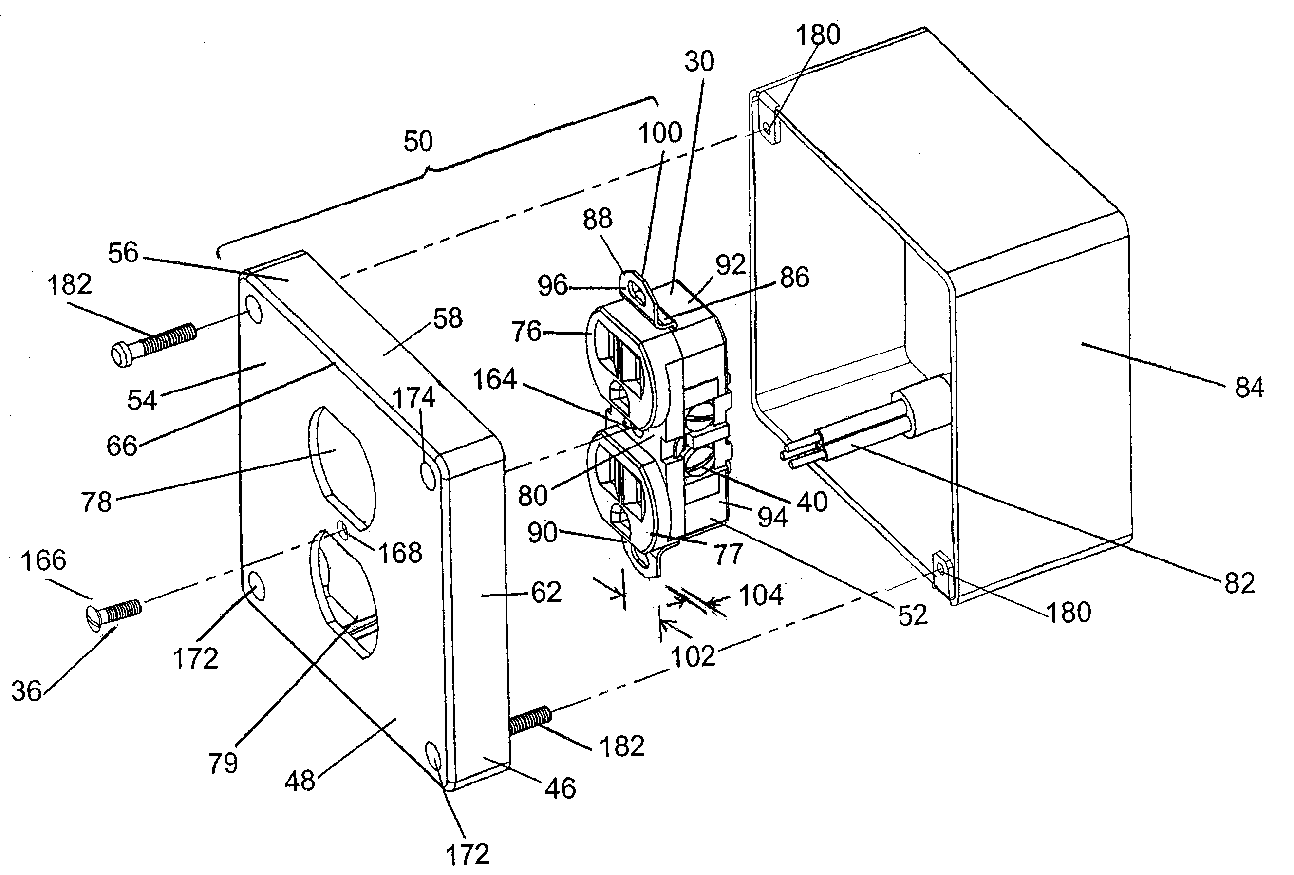
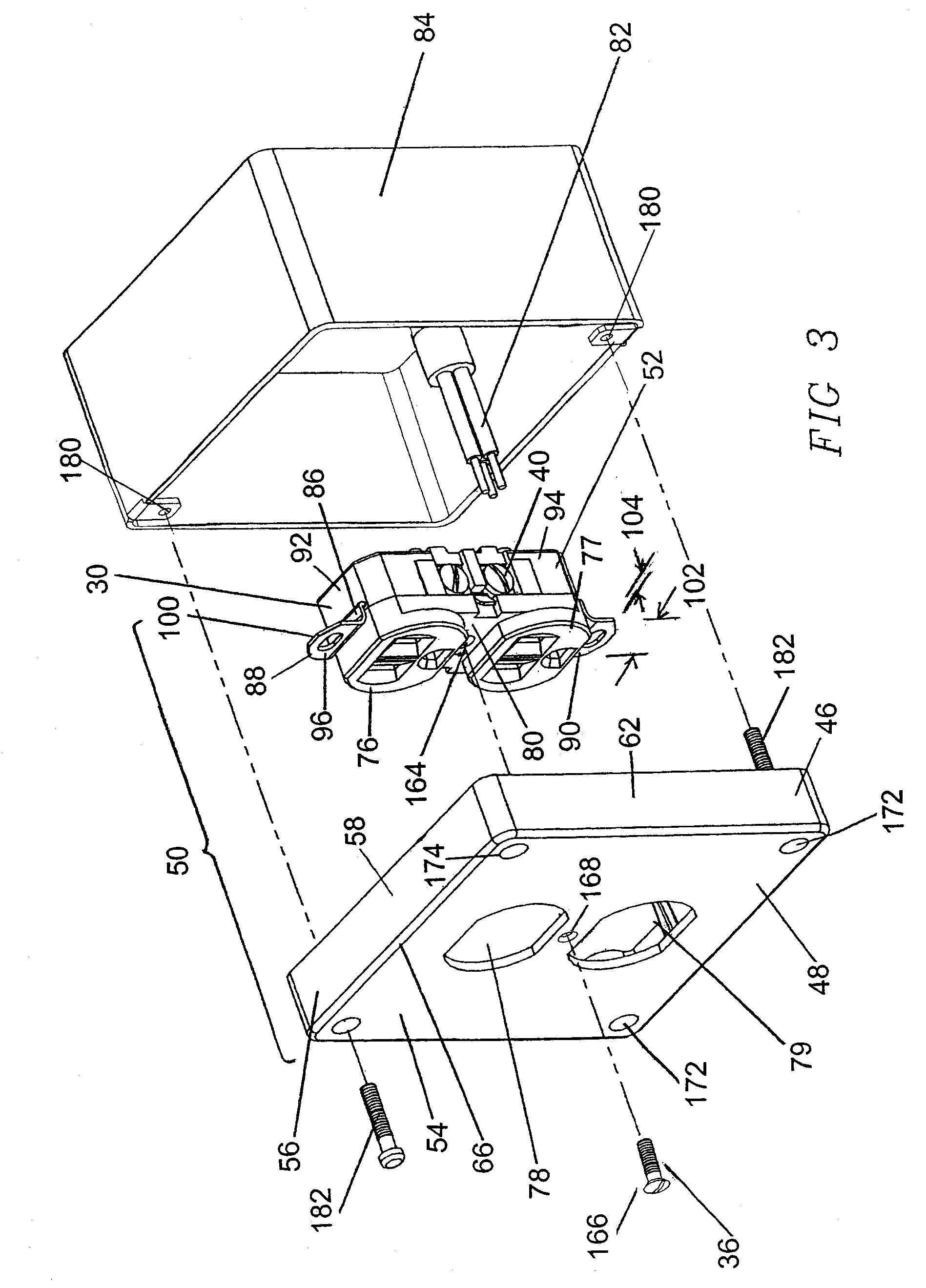
[0058]FIGS. 3-13B illustrate preferred embodiments of an improved cover plate to which a conventional electrical circuit device is attached to form a cover plate assembly in accordance with this invention. Identical reference numbers refer to similar features throughout this description. Cover plate and circuit device are quickly and easily assembled together without the need for the application of any adhesive such as glue or the use of any fasteners such as threaded screws and nuts to hold them.

[0059]One embodiment is cover plate assembly 50 as shown in FIGS. 3-5. Cover plate assembly 50 has a cover plate 48 and a double outlet electrical receptacle 52 as the electrical circuit device 30 engaged to cover plate 48. While cover plate 48 can be made from a flexibly resilient metal, it is more preferably a monolithic structure that has been fabricated from a polymeric material with the desired flexibility, strength and flame resistence. In addition to these properties, the choice of p...


PUM


Abstract

A cover plate assembly for mounting an electrical circuit device to an electrical outlet box includes at least one electrical circuit device and a cover plate. The cover plate has a locking member rigidly mounted to its rear surface, whereby the attachment member mounted upon the electrical circuit device is slidably received and restrained by the locking member to secure the electrical circuit device to the cover plate utilizing only the locking member. The locking member is preferably at least two flexibly resilient panels spaced apart so that each panel contacts the attachment member when inserted into the locking member. Both panels are preferably rigidly mounted to the cover plate's interior surface and have inner surfaces sloping outward from their lower edge so that the distance is greatest between their upper edges. These panels are spaced above the cover plate's back face by a distance substantially equal to the attachment member's depth to restrain the attachment member beneath the locking member when it is inserted through the locking member. A method for installing an electrical circuit device to an electrical outlet box is also disclosed.

Description

FIELD OF THE INVENTION[0001]This invention is related generally to cover plate assemblies for electrical outlet boxes and, more particularly, cover plate assemblies for surface mounted electrical outlet boxes.BACKGROUND OF THE INVENTION[0002]Prevailing building and safety codes such as the National Electrical Code of the National Fire Protection Association, which has been adopted by many states and municipalities, require that electrical wiring connections to electrical circuit devices from an electrical circuit or electrical conduit occur in an enclosed electrical outlet or junction box housing.[0003]The electrical outlet box is available in a variety of styles and shapes, but each has a concave interior cavity with a substantially planar opening. Cover plates (also called face plates) for these boxes have openings of various standard sizes and shapes to accommodate the exterior interface portions of the electrical circuit devices. When the electrical circuit device is securely at...

Claims


Application Information

Patent Timeline
IPC IPC(8): H02G3/14
CPCH02G3/14
Inventor PINKOWSKI, MARVIN
Owner TREMAR CORP
Why Eureka
Try Eureka