Appliance data collecting system

a data collection and application technology, applied in wireless systems/telephones, electric controllers, instruments, etc., can solve the problems of terminals not being able to display the correct data on the screen, communication efficiency deterioration, display response degraded,

Inactive Publication Date: 2005-01-04
PANASONIC CORP
View PDF8 Cites 62 Cited by
  • Summary
  • Abstract
  • Description
  • Claims
  • Application Information

AI Technical Summary

Benefits of technology

In view of the foregoing, it is the object of the present invention to provide a home network system that can display non-collected data even if there is a time period when the data on the appliances are not acquired in the display terminal.
In doing this, the display terminal device can acquire the appliance data from each appliance regularly and complement the appliance data during the non-collected time period from the control device.
In doing this, the display terminal device can acquire the appliance data from each appliance regularly and complement the non-collected appliance data at the time of startup and regularly from the control device.
In doing this, the display terminal device can acquire the appliance data from each appliance regularly, complement the non-collected appliance data at the time of startup and regularly from the control device and correct the time of the built-in clock based on the clock of the control device.

Problems solved by technology

In this case, the display terminal cannot collect data while it is not connected to the electric power line, and therefore there is a drawback that the display terminal cannot display the correct data on the screen even though it tries to refer to the past data because the data are not acquired.
Additionally, in the system that the storage capacity of the display terminal is not enough to hold the large quantity of data on the appliances and therefore the display terminal must acquire the data from a controller every time it displays the data.
Further, when the display terminal analyzes and displays the data frequently or the data quantity is large, there is also a problem that the communication quantity becomes enormous, communication efficiency deteriorates and furthermore the display response is degraded.

Method used


Image

  • Appliance data collecting system
  • Appliance data collecting system
  • Appliance data collecting system

Examples


first embodiment

(The First Embodiment)

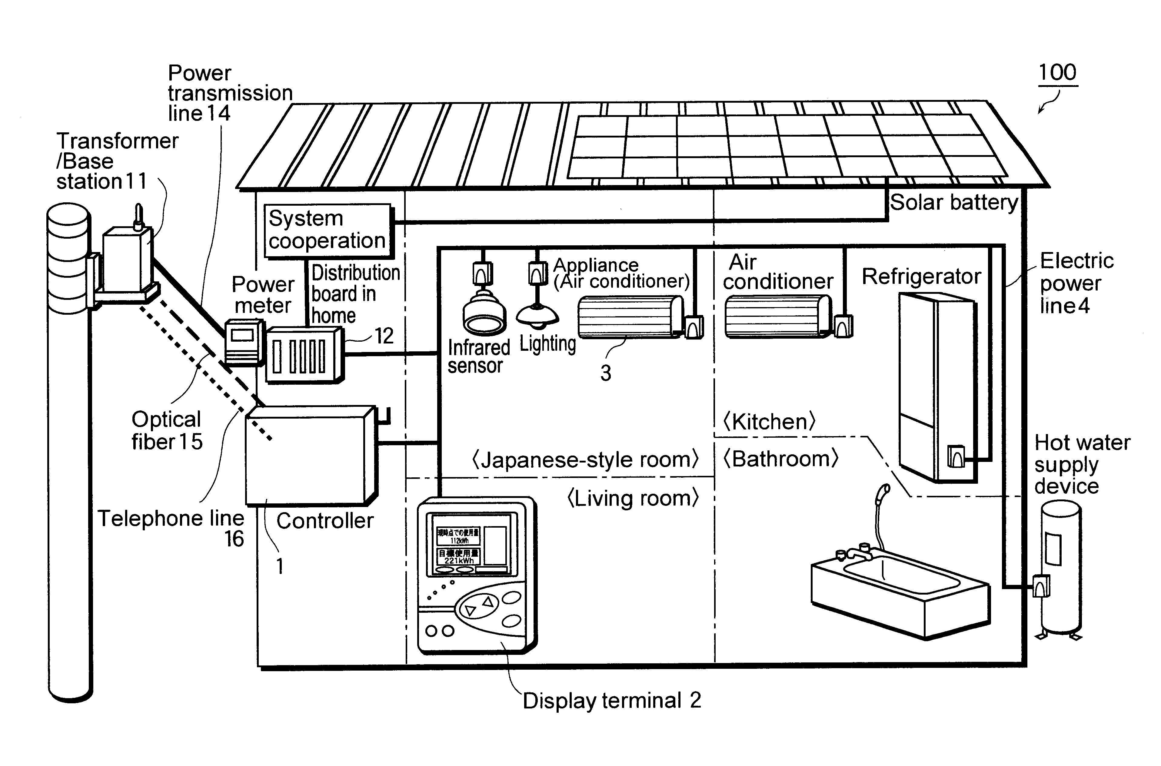
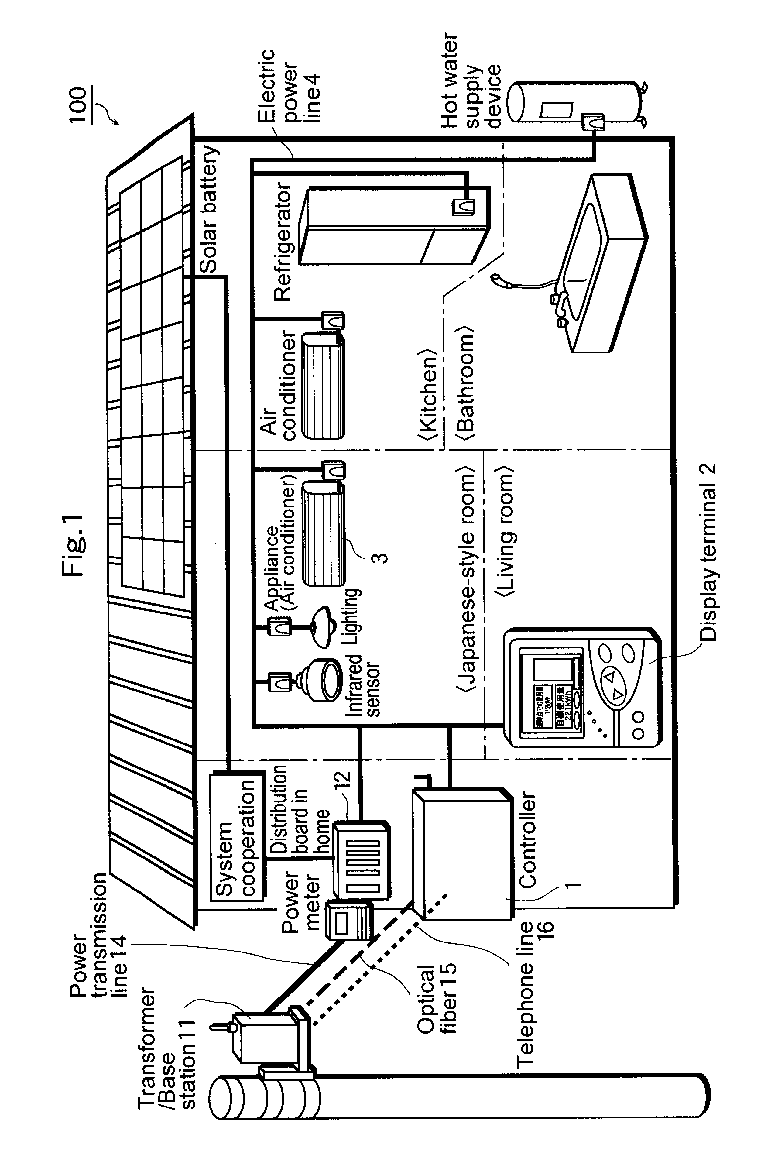
FIG. 1 is a diagrammatic sketch of an appliance data collecting system 100 according to the first embodiment. This appliance data collecting system 100 has a form of LAN (Local Area Network) using an electric power line receives power supply through an outside transformer 11 and an outside power transmission line 14 and is connected with an outside network (such as Internet) through an optical fiber 15, a telephone line 16 and the like. To be more specific, the appliance data collecting system 100 is connected with a controller 1, a display terminal 2, an appliance 3 and the like through an indoor electric power line 4 and exchange data on appliances (hereafter, referred to as “appliance data”) each other. Here, concrete examples of the appliance data are data on the use situation and the like of the appliance 3 such as the total amount of electricity and the used hours, data that represent an operation from a user to the display terminal 2, various control dat...

second embodiment

(The Second Embodiment)

In the second embodiment, a working example of correcting the time that is one of the important appliance data to collect the non-acquired appliance data with reliability in the appliance data collecting system is explained.

FIG. 18 is a block diagram that shows the structure of the appliance data collecting system 200 according to the present embodiment and the functional structure of each device. As is shown in FIG. 18, the present system 200, similarly to the appliance data collecting system 100 according to the first embodiment, is equipped with a controller 19, a display terminal 20 and an appliance 3 and each device is connected through an electric power line 4. The respect in which this appliance data collecting system 200 is different from the appliance data collecting system 100 is the respect that a center server 17 is set outdoors. Moreover, the same structure as that of the first embodiment is given the same letter symbol and its explanation is omit...

third embodiment

(The Third Embodiment)

In the third embodiment, a working example in the case of collecting data on the user's operations as an example of the appliance data and of losing the data in the appliance data collecting system is explained.

FIG. 30 is a block diagram that shows a structure of the data collecting system 300 according to the third embodiment and the functional structures of each device. As is shown in FIG. 30, the present system 300, similarly to the appliance data collecting system 200 according to the second embodiment, is equipped with a controller24, a display terminal 25, a center server 28 and an appliance 3 and each device is connected through an electric power line 4 or a communication line 18 The respect in which this appliance data collecting system 300 is different from the appliance data collecting system 200 is the respect that the controller 24 is equipped with a display terminal operation history holding unit 26, the display terminal 25 is equipped with a displ...


PUM


Abstract

A controller (1) holds appliance data acquired from an appliance (3) regularly and without loss. A display terminal (2) is capable of moving to other rooms through a receptacle and holds the appliance data acquired from the appliance (3). When there is loss in the appliance data for a part of time period because of a move and the like, the display terminal (2) executes acquisition request to the controller (1) to acquire this non-collected data of the appliance. The controller (1) transmits the appliance data to the display terminal (2) in response to the request of the display terminal (2). The display terminal (2) acquires (or complements) the non-collected data from the controller (1) and display the data.

Description

BACKGROUND OF THE INVENTION(1) Field of the InventionThe present invention relates to communication system using an electric power line and particularly relates to data collecting technology on electric household appliances in electric power line communication system at home.(2) Description of the Prior ArtConventionally, technology of collecting data from appliances using an electric power line in home network is disclosed in the Japanese Laid-Open Patent Application Nos. H7-312649 and H10-271572. The technology of the Japanese Laid-Open Patent Application No. H7-312649 is a system in which a power transmission communication device collects sampling data held in plural terminals through an electric power line. The technology of the Japanese Laid-Open Patent No. H10-271572 is a system in which an information collecting device collects meter-reading information of a power meter placed in each household and information of a home-care support system, a household security service suppor...

Claims


Application Information

Patent Timeline
Patent Type & Authority Patents(United States)
IPC IPC(8): H04B3/54H04L12/28
CPCH04B3/54H04B2203/5408H04B2203/5441H04B2203/5445H04L2012/2843H04B2203/5495H04L12/2803H04L12/281H04B2203/5479
Inventor AIZU, KAZUHIROSHINTANI, YASUYUKIMURAKAMI, TAKASHI
Owner PANASONIC CORP
Why Eureka
Try Eureka