Plasma display with split electrodes

a technology of split electrodes and plasma, applied in the manufacture of electrode systems, electric discharge tubes/lamps, instruments, etc., can solve problems such as vertical crosstalk, and achieve the effect of increasing brightness and minimizing vertical crosstalk

Inactive Publication Date: 2005-02-08
PANASONIC CORP
View PDF10 Cites 28 Cited by
  • Summary
  • Abstract
  • Description
  • Claims
  • Application Information

AI Technical Summary

Benefits of technology

The present invention relates to a pixel architecture for plasma display panels. Electrodes of the pixels are controlled to minimize vertical crosstalk between pixels and provide for increased brightness.
Still another method of controlling electrodes of a pixel in a plasma display panel includes (a) applying a voltage waveform to an outer sustain electrode of the pixel, (b) applying a voltage waveform to an inner sustain electrode of the pixel, (c) applying a voltage waveform to an inner scan electrode of the pixel, and (d) applying a voltage waveform to an outer scan electrode of the pixel. The voltage waveform to the outer sustain electrode, the voltage waveform to the inner sustain electrode, the voltage waveform to the inner scan electrode and the voltage waveform to the outer scan electrode have relationships that (i) discourage an addressing discharge involving the inner sustain electrode and the inner scan electrode from extending to the outer sustain electrode and the outer scan electrode, and (ii) permit a sustaining discharge involving the inner sustain electrode and the inner scan electrode to extend to the outer sustain electrode and the outer scan electrode.
Yet another apparatus includes (a) a circuit for applying a voltage waveform to an outer sustain electrode of a pixel in a plasma display panel, (b) a circuit for applying a voltage waveform to an inner sustain electrode of the pixel, (c) a circuit for applying a voltage waveform to an inner scan electrode of the pixel, and (d) a circuit for applying a voltage waveform to an outer scan electrode of the pixel. The voltage waveform to the outer sustain electrode, the voltage waveform to the inner sustain electrode, the voltage waveform to the inner scan electrode and the voltage waveform to the outer scan electrode have relationships that (i) discourage an addressing discharge involving the inner sustain electrode and the inner scan electrode from extending to the outer sustain electrode and the outer scan electrode, and (ii) permit a sustaining discharge involving the inner sustain electrode and the inner scan electrode to extend to the outer sustain electrode and the outer scan electrode.

Problems solved by technology

However, there is a possibility of vertical crosstalk resulting from the electrodes on either side of the inter-pixel gap being driven with the same potential.

Method used


Image

  • Plasma display with split electrodes
  • Plasma display with split electrodes
  • Plasma display with split electrodes

Examples


Embodiment Construction

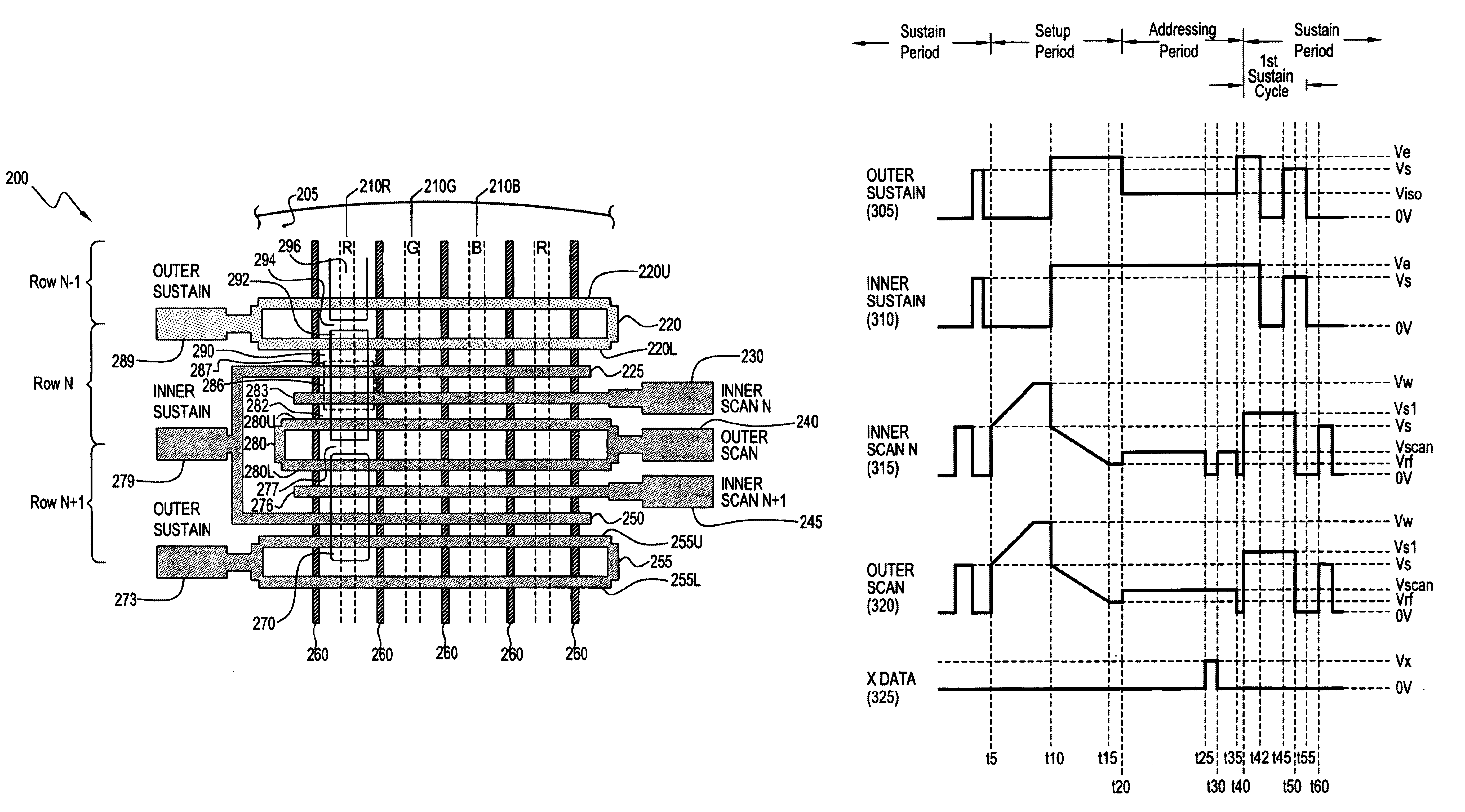
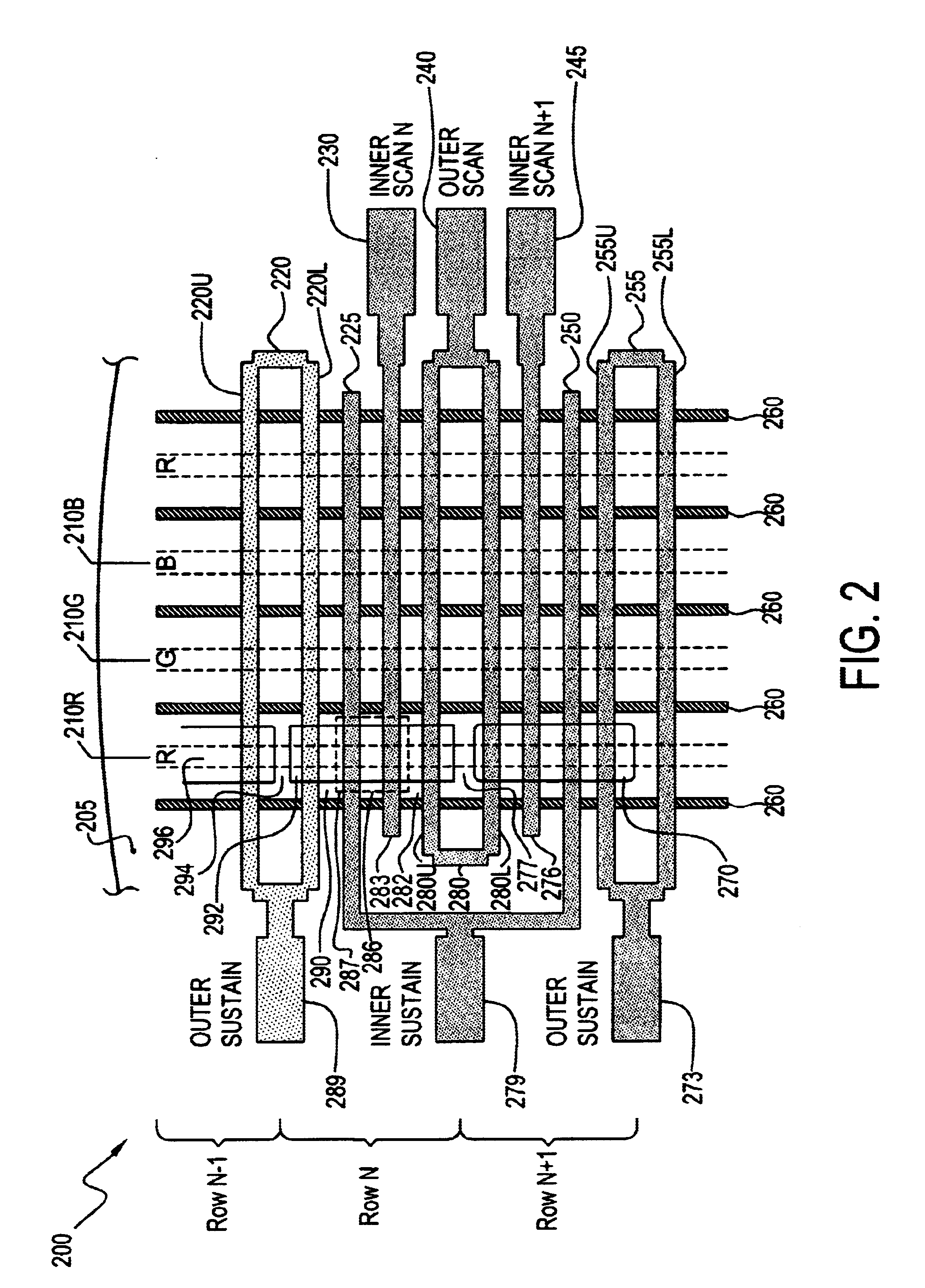
Elimination or suppression of vertical crosstalk between pixels allows for minimization of the size of an inter-pixel gap to maximize the pixel size thereby increasing brightness.

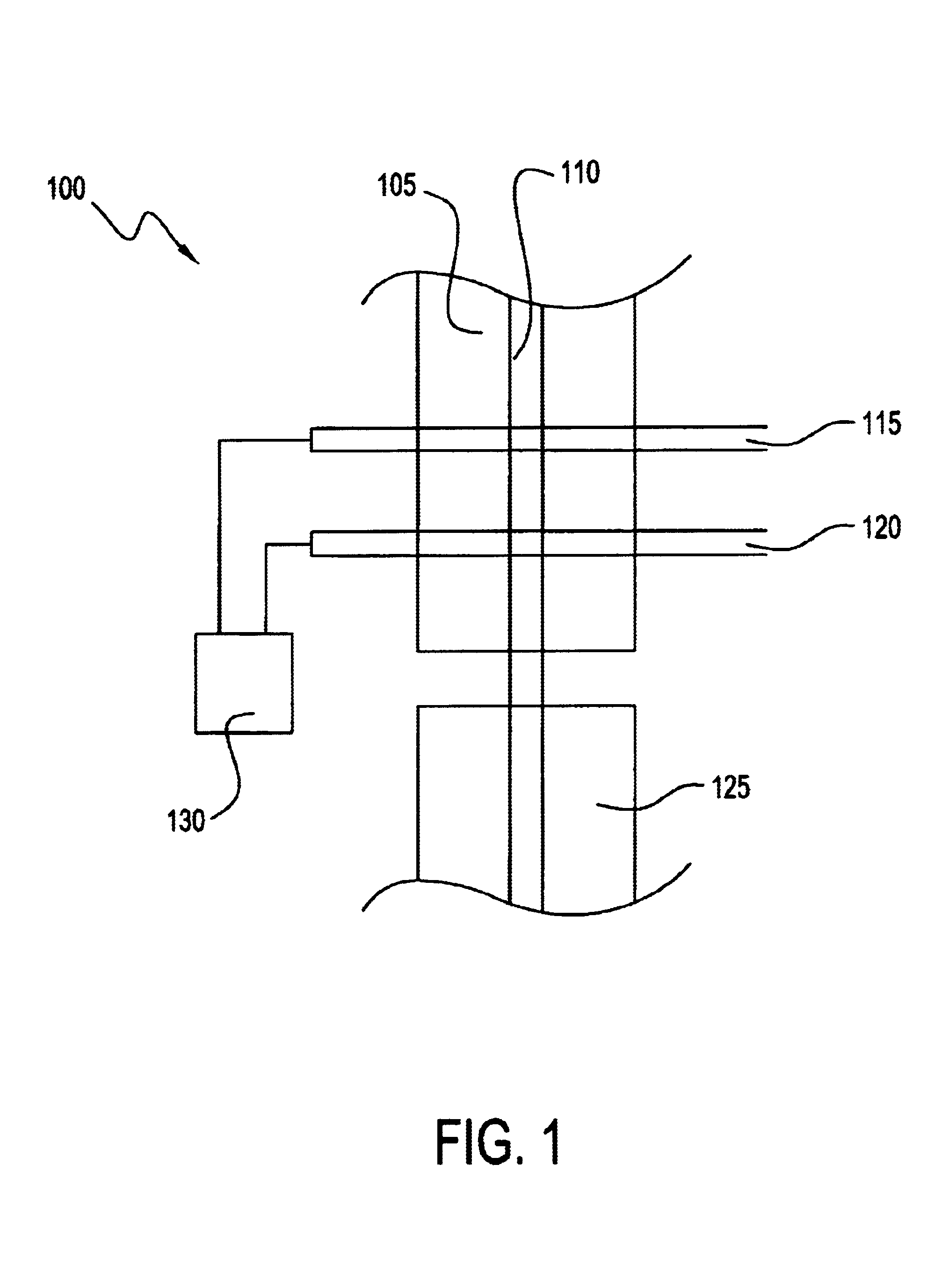
FIG. 1 is an illustration of a portion of a PDP 100, and more particularly a portion of a pixel 105 located at an intersection of a first electrode 115, a second electrode 120 and a data electrode 110. A controller 130 applies voltages to first electrode 115 and second electrode 120 to provide control of first electrode 115 and second electrode 120 independently of one another. The first voltage and the second voltage influence whether a discharge involving first electrode 115 extends to second electrode 120. First electrode 115 and second electrode 120 may operate as a split electrode.

During an addressing period, an addressing discharge is initiated between data electrode 110 and first electrode 115. During the addressing discharge, controller 130 applies a first voltage to first electrode 115, and applies...


PUM


Abstract

There is provided a method of controlling electrodes of a pixel in a plasma display panel. The method includes applying a first voltage to a first electrode of the pixel during an addressing discharge involving the first electrode, and applying a second voltage to a second electrode of the pixel. The first voltage and the second voltage have a relationship that discourages the addressing discharge from extending to the second electrode.

Description

BACKGROUND OF THE INVENTION1. Field of the InventionThe present invention relates to plasma display panels, and more particularly, to a pixel architecture that minimizes vertical crosstalk between pixels and increases brightness.2. Description of the Related ArtColor plasma display panels (PDPs) are well known in the art. Visible light is emitted by phosphors within the panel in response to gas plasma discharges between a pixel's sustain and scan electrode. During an addressing period, sustain electrodes are generally driven with a common potential, while scan electrodes are selected individually. Since the electrodes are on an internal surface of a front plate, the light produced must pass through the electrodes. When transparent electrodes, e.g., indium tin oxide (ITO), are employed, the light simply passes through the electrode. Alternatively, non-transparent apertured electrodes may be devised that allow the light to pass through open apertures in the electrode.An embodiment of ...

Claims


Application Information

Patent Timeline
Patent Type & Authority Patents(United States)
IPC IPC(8): G09G3/28H01J17/49G09G3/20G09G3/291G09G3/296G09G3/298H01J9/02H01J11/12H01J11/22H01J11/24H01J11/26H01J11/32H01J11/34
CPCG09G3/2983H01J11/12H01J11/32G09G3/291G09G3/296H01J2211/323G09G2320/0209G09G2310/0218
Inventor MARCOTTE, ROBERT G.
Owner PANASONIC CORP
Why Eureka
Try Eureka