Vehicle headrest apparatus

a headrest and vehicle technology, applied in the direction of vehicular safety arrangements, chairs, pedestrian/occupant safety arrangements, etc., can solve the problems of reducing the protective effect of airbags, imposing a severe stress on the ears of passengers, and the headrest units cannot be moved sufficiently forward, so as to reduce the headrest restraining effect

Inactive Publication Date: 2005-03-08
NISSAN MOTOR CO LTD
View PDF11 Cites 38 Cited by
  • Summary
  • Abstract
  • Description
  • Claims
  • Application Information

AI Technical Summary

Benefits of technology

[0008]It has been discovered that in the above mentioned seatback systems that the headrests are actuated using the inertia force of the seated passenger. Thus, these headrest units do not begin moving forward until the rearward displacement of the pas

Problems solved by technology

Consequently, these head rest units cannot be moved sufficiently forward during the period immediately after the collision when the amount of displacement is still small.
This imposes a severe stress on the passenger's ears.
In add

Method used


Image

  • Vehicle headrest apparatus
  • Vehicle headrest apparatus
  • Vehicle headrest apparatus

Examples


first embodiment

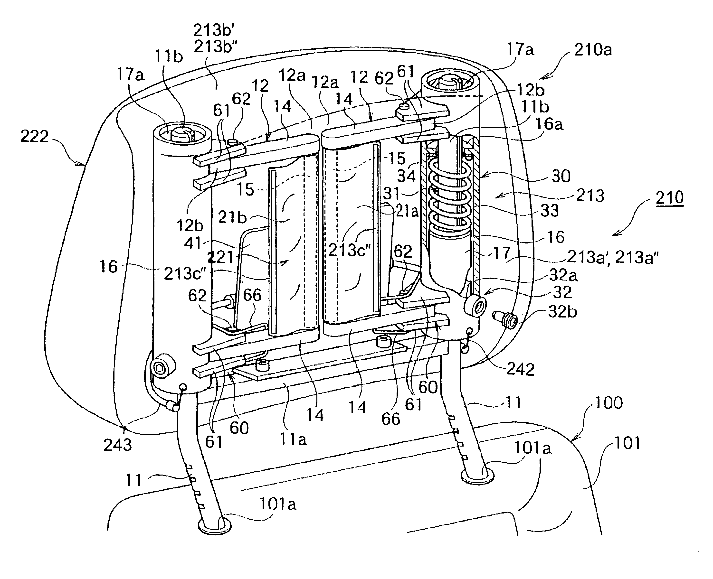
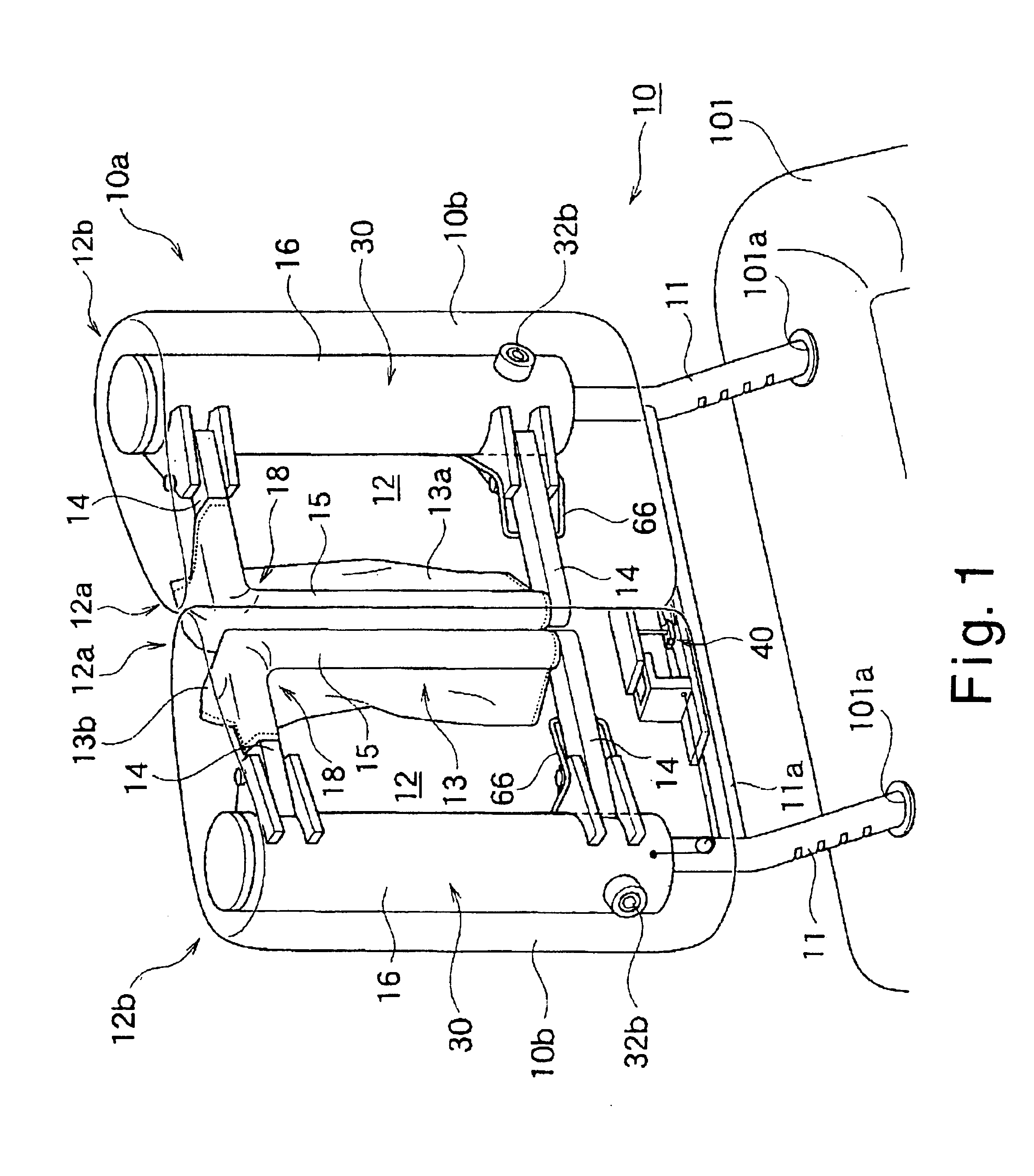
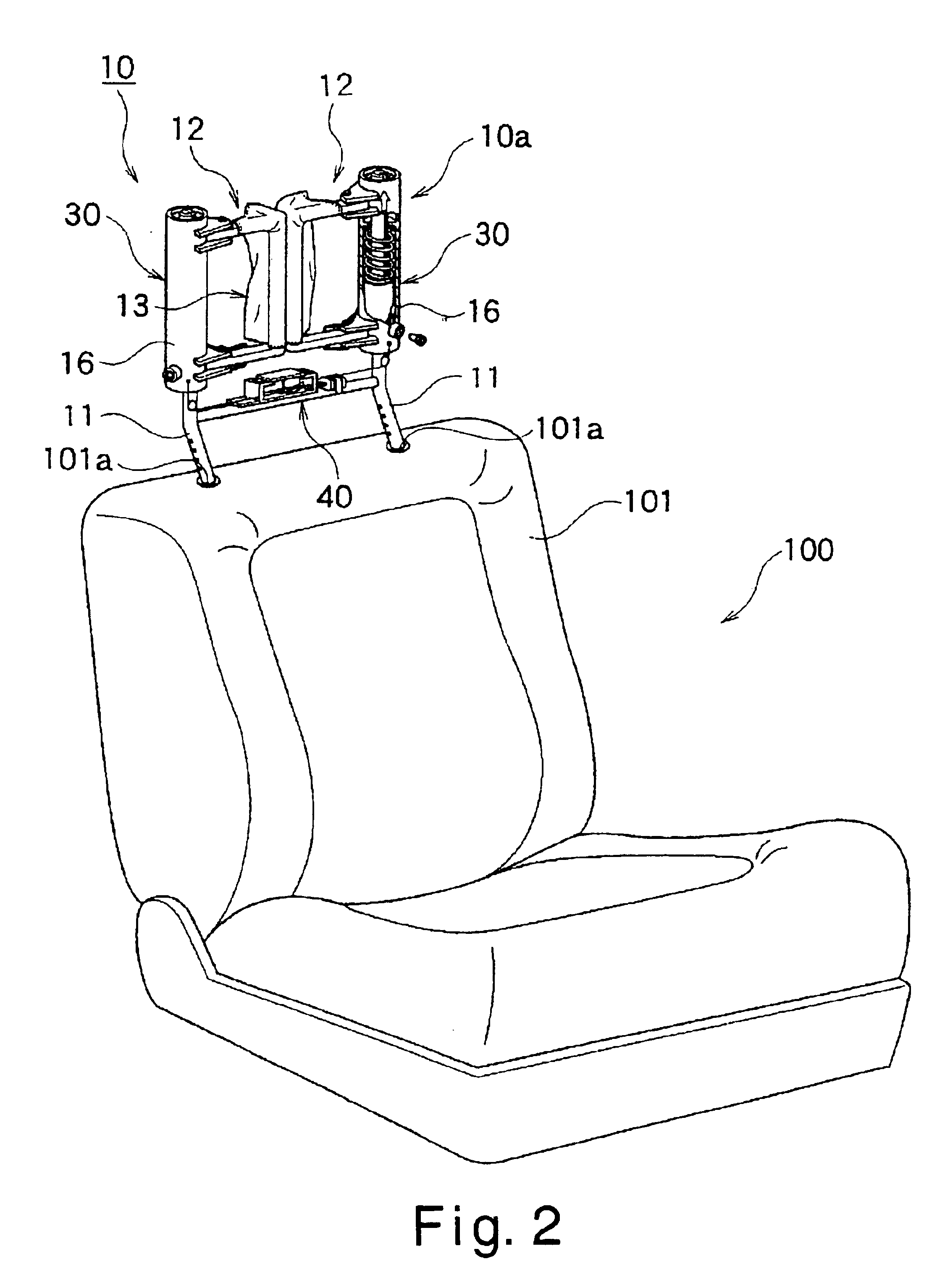
[0074]Referring initially to FIGS. 1 to 18, the vehicle headrest apparatus 10 is illustrated in accordance with a first embodiment of the present invention. FIG. 1 is a front perspective view of the headrest unit in an initial state. FIG. 2 is an overall perspective view of a seat installed with the headrest unit. FIG. 3 is an enlarged perspective view of the headrest unit depicting a main component in a cross-sectional manner. As shown in FIGS. 1 to 3, the vehicle headrest apparatus 10 of this embodiment includes a headrest unit 10a with a mounting member comprising a pair of stays 11. The vehicle headrest apparatus 10 is adjustably coupled to a vehicle seat 100 by the stays 11. More specifically, the vehicle headrest apparatus 10 is attached to the upper end part of a seatback 101 of the vehicle seat 100. Thus, the headrest unit 10a is arranged to support the head of a seated passenger sitting in the vehicle seat 100. The stays 11 of the headrest unit 10a are mounted in a pair of ...

second embodiment

[0140]Referring now to FIGS. 19 to 21, a vehicle headrest apparatus 10′ in accordance with a second embodiment will now be explained. Basically, the headrest apparatus 10′ is identical to the headrest apparatus 10, as discussed above, except that a modified flexible sheet restraining member 13′ is used instead of the sheet member 13 of the first embodiment. In view of the similarity between the first and second embodiments, the parts of the second embodiment that are identical to the parts of the first embodiment will be given the same reference numerals or symbols as the parts of the first embodiment. Moreover, the descriptions of the parts of the second embodiment that are identical to the parts of the first embodiment may be omitted for the sake of brevity.

[0141]FIG. 19 is a perspective view of the headrest apparatus 10′ in the completely deployed state with the cushion pad removed. FIG. 20 is a rear perspective view of the headrest apparatus 10′ in the completely deployed state....

third embodiment

[0148]Referring now to FIGS. 22 to 24, a vehicle headrest apparatus 10″ in accordance with a third embodiment will now be explained. Basically, the headrest apparatus 10″ is identical to the headrest apparatus 10, as discussed above, except that a modified flexible sheet restraining member 13″ is used instead of the sheet member 13 of the first embodiment. In view of the similarity between the third embodiment and the prior embodiments, the parts of the third embodiment that are identical to the parts of the prior embodiments will be given the same reference numerals or symbols as the parts of the prior embodiments. Moreover, the descriptions of the parts of the third embodiment that are identical to the parts of the prior embodiments have been omitted for the sake of brevity.

[0149]FIG. 22 is an enlarged cross-sectional perspective view of the main components of the headrest apparatus 10″. FIG. 23 is a rear perspective view of the headrest apparatus 10″ in the completely deployed st...


PUM


Abstract

A vehicle headrest apparatus has a headrest unit that is mounted to an upper end of a seatback. The headrest unit has a head restraining member with a flexible sheet restraining member configured to be tensioned to restrain a passenger's head when a controller detects a rear-end collision. The head restraining member has a vertical support portion facing the head of the passenger and a horizontal support portion substantially perpendicular to an upper part of the vertical support portion. When a rear-end collision occurs, tension is applied to at least the vertical support portion. In some embodiments, the vertical and horizontal support portions are both formed by the flexible sheet restraining member. In other embodiments, only the vertical support portion is partially formed by the flexible sheet restraining member, and the vertical and horizontal support portions are made of a resilient material having an excellent shape-retaining property.

Description

BACKGROUND OF THE INVENTION[0002]1. Field of the Invention[0003]The present invention generally relates to a vehicle headrest apparatus that is used on a vehicle seat and supports the head of a seated passenger. More specifically, the present invention relates to a vehicle headrest apparatus that is configured to reliably restrain a passenger's head and suppress the rearward movement of a passenger's head when a rear-end collision occurs by actuating a headrest unit itself.[0004]2. Background Information[0005]An example of an automobile seatback system is disclosed in Japanese Laid-Open Patent Publication No. 7-291005 in which the seatback is designed to protect the head of a seated passenger in the event of a rear-end collision. In particular, this Japanese publication discloses a seatback that bears the dynamic load acting on a seated passenger due to the inertia force when a vehicle is subjected to a rear-end collision. The movement of a member that is displaced as a result is tr...

Claims


Application Information

Patent Timeline
IPC IPC(8): B60N2/48
CPCB60N2/4864B60N2/4885B60N2002/022B60N2/888B60N2/865
Inventor PAL, CHINMOYKOBAYASHI, IZUMI
Owner NISSAN MOTOR CO LTD
Why Eureka
Try Eureka