Aerosol can

Inactive Publication Date: 2005-04-12
THOMAS SA
View PDF20 Cites 21 Cited by
  • Summary
  • Abstract
  • Description
  • Claims
  • Application Information

AI Technical Summary

Benefits of technology

is based on providing a spray can having the mentioned safety feature, which does not require any special steps in manufacturing the valve disk or the can body for obtaining fixed turning stops, and allows the use of the same stop ring, regardless of the thickness of the material of the valve disk.
The proposed spray can has the advantage that, after the valve disk has been fastened by cramping it on the flanged rim of the opening of the can body, the stop ring can be simply and dependably fixed in place pushing it into the annular space between the valve dome and the collar in such a way that it rests with a solid press fit against the collar and / or the dome. Thus it is not necessary to produce specially designed valve disks for such spray cans with safety functions. The press fit of the stop ring on the collar can easily be embodied in such a way that by this alone a very strong holding moment is achieved.
Moreover, the embodiment of the outer circumferential surface of the stop ring with lamellas allows the adaptation to different inner diameters of the collar of the valve disk. A single stop ring for all customary material thicknesses of the valve disk is therefore sufficient.
In the preferred embodiment, the lamellas extend outward from their origin at an acute angle to the respective radial direction. In this way the lamellas are primarily stressed for bending in the press fit and are not merely radially upset. The adaptation to the different inner diameters of the collar is provided by a more or less strong bending of the lamellas.

Problems solved by technology

However, this is often forgotten, and just a moment of carelessness is sufficient to trigger a burst of spray.

Method used


Image

  • Aerosol can
  • Aerosol can
  • Aerosol can

Examples


Embodiment Construction

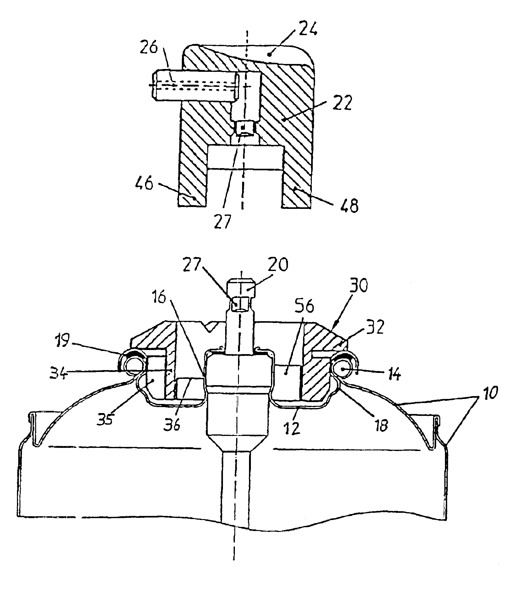
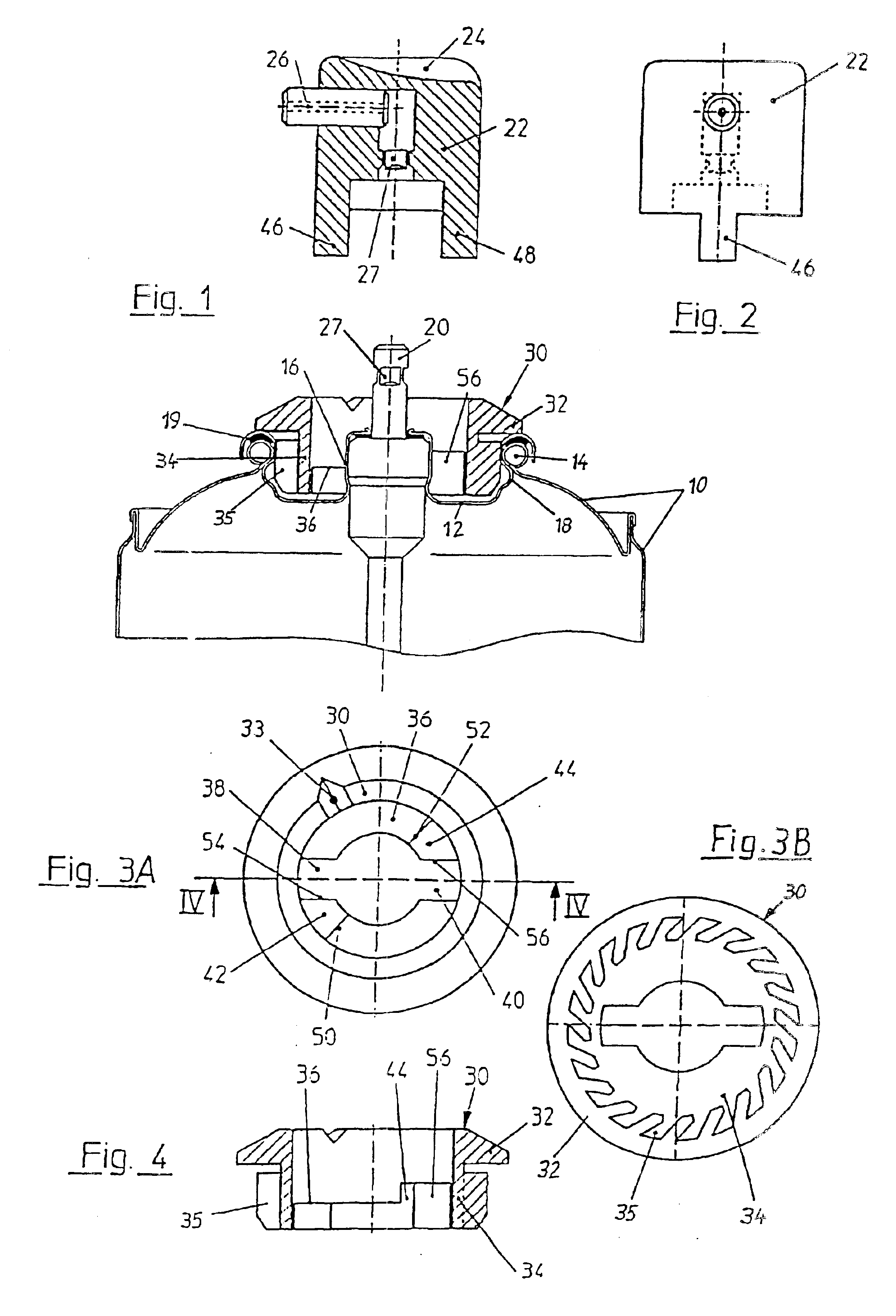
The upper portion of a spray can, whose body is identified by 10 and whose valve disk by 12, is represented in FIG. 1. It is of no importance to the invention whether the can body was made in several parts of tin plate or in one piece of an aluminum alloy. In both cases the container opening, which is provided with a flange 14, is sealed by means of an appropriate valve disk 12 fastened on it, which has been designed in the customary way with a valve dome 16 in its center area and with a collar 18 extending concentrically around the dome in its radially outer area. The valve dome 16 contains parts of the spray valve, while the collar 18 has been fastened on the flanged rim 14 of the can body 10 by cramping, wherein a seal ring 19, or a sealing material laminated on it, provides tight closing.

A tappet 20 extends upward out of the valve dome which, on one hand, is the actuating tappet of the spray valve in the dome 16 and, on the other hand, constitutes the outlet conduit for the flui...


PUM


Abstract

The spray can has a valve disk (12) with a valve, which valve disk is formed with a valve dome (16) and a fastening collar (18) surrounding it at a radial intermediate distance. The valve is actuated by pushing down a rotatable spray head (22) seated on a tappet (20). For obtaining turning stops for an actuating position and a closing position without taking special steps on the valve disk (12) or can body (10), it is provided that a stop ring (30) is arranged, fixed against relative rotation, in the annular space between the valve dome (16) and the collar (18). For being adaptable to materials of different thickness of the valve disk (12), it is formed with lamellas (35) at the outer circumference, is pushed with press fit into the collar (18) and has a cam track (36) with at least one recess extending along the circumference. The spray head (22) is formed or connected with at least one cam (46, 48). It acts together with turning stop faces (56) on the stop ring (30). Acting together with the cam track (36), it permits the spray head (22) to be pushed down only if the cam (46) is located above the recess.

Description

BACKGROUND OF THE INVENTIONThe invention relates to a spray can with a valve disk with a valve, which is formed with a valve dome and a fastening collar surrounding the latter at a radial intermediate distance, as well as with a rotatable spray head, which can be placed on a tappet extending upward out of the valve dome and being axially movable for controlling the valve, and together with the latter must be pushed downward against a spring force from a closed position into a spraying position, wherein a stop ring has been pushed and is seated by press fit, fixed against relative rotation, in the collar (30, 92), on the upward pointing side of which a cam track, extending along the circumference, has been formed, over which, when the spray head is rotated into the closed position, one or several cams connected with it can be moved at a slight distance or slidingly, while at least one stop connected with it can be rotated back and forth between two stop faces extending transversely t...

Claims


Application Information

Patent Timeline
Patent Type & Authority Patents(United States)
IPC IPC(8): B65D83/16B65D83/14B05B11/00B65D83/34B21D51/26B65D83/36
CPCB65D83/205B65D83/22B65D2215/04B65D83/40
Inventor SCHNEIDER, HEINZ
Owner THOMAS SA
Why Eureka
Try Eureka