Tool display member

a technology for displaying members and tools, which is applied in the field of tools display members, can solve the problems of damage to the display members themselves, the tool is not securely positioned on the tool display members,

Inactive Publication Date: 2005-04-26
LEE DANIEL
View PDF11 Cites 34 Cited by
  • Summary
  • Abstract
  • Description
  • Claims
  • Application Information

AI Technical Summary

Benefits of technology

[0005]The present invention will become more obvious from the following description when taken in connection with the accompa

Problems solved by technology

Although the conventional tool display member has been used for a long period of time, it is noticed that the tool is not positioned securely on the tool display member because the tools have different shapes and thickness which may not meet the condition of the conventional tool display member and therefore the tool can be shifted and this could damage the display member itself.

Method used


Image

  • Tool display member
  • Tool display member
  • Tool display member

Examples


Embodiment Construction

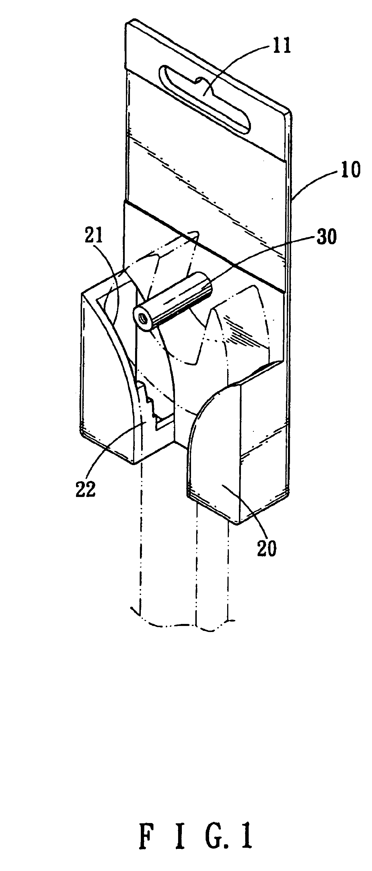
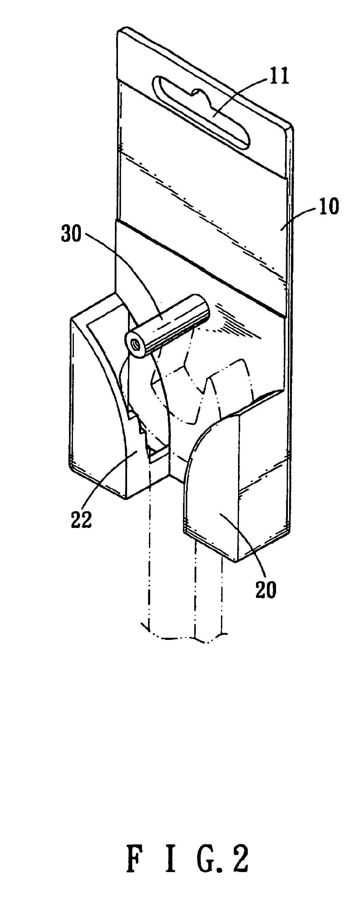
[0012]Referring to FIGS. 1 to 3, the tool display member of the present invention comprises a board 10 through which a slot 11 is defined so that the board 10 can be hung on a wall. Two side pieces 20 are connected to a first side of the board 10 and a gap is defined between the two side pieces 20. Each sidepiece 20 has an opening 21 defined in an inside thereof and a protrusion 22 extends from an inside of the opening 21. Each of the protrusions 22 has a stepped edge and different width of gaps is defined between the stepped edge and the first side of the board 10. The stepped edge is formed vertical to the board 10. Therefore, tools such as wrench or pliers can be supported between the two sidepieces 20 and a head of the tool can be clamped between one of the stepped surfaces of the stepped edge and the first side of the board 10. In other words, the tools having different thickness can be securely clamped by the stepped edge.

[0013]Referring to FIGS. 4 to 6, a rod 30 extends from ...


PUM


Abstract

A tool display member includes a board and two side pieces are connected to a first side of the board. A gap is defined between the two side pieces and each side piece has an opening defined in an inside thereof. A protrusion extends from an inside of each of the opening and includes a stepped edge so that a tool can be supported and clamped between the stepped edges. A locking plate is fixed to the board and connected between the two side pieces.

Description

FIELD OF THE INVENTION[0001]The present invention relates to a tool display member having two side pieces on the board of the display member and each side piece has stepped protrusion so as to accommodate the tool of different thickness.BACKGROUND OF THE INVENTION[0002]A conventional tool display member generally includes a board with a hole or slot so that the board is able to be hung on a wall and a tool is fixed to the board so that the tool can be displayed clearly without too much being covered or hidden. Although the conventional tool display member has been used for a long period of time, it is noticed that the tool is not positioned securely on the tool display member because the tools have different shapes and thickness which may not meet the condition of the conventional tool display member and therefore the tool can be shifted and this could damage the display member itself. Besides, most of the conventional tool display members only provide a place for the tool to be att...

Claims


Application Information

Patent Timeline
IPC IPC(8): B65D5/4805B65D5/02B65D5/10B65D5/48B65D85/20
CPCB65D5/02B65D5/10B65D85/20B65D5/48014Y10S206/806B65D2301/20
Inventor LEE, DANIEL
Owner LEE DANIEL
Why Eureka
Try Eureka