Terminal

a technology of terminals and connectors, applied in the direction of coupling contact members, coupling device connections, securing/insulating coupling contact members, etc., can solve the problems of deformation of side walls, deformation of circumferential walls of holes in sealing members, and springs that might be deformed, so as to ensure the strength of terminals and reduce load on the body , the effect of enhancing the strength of the body

Active Publication Date: 2005-06-14
JST MFG CO LTD
View PDF13 Cites 38 Cited by
  • Summary
  • Abstract
  • Description
  • Claims
  • Application Information

AI Technical Summary

Benefits of technology

[0011]The present invention was made in view of these points, and its objective is to provide a terminal, wherein a rectangular-tube-shaped body of the terminal comprises a cross plate, two vertical plates rising from both ends in the width direction of the cross plate, and an inner plate and an outer plate both extending from the vertical plates in the width direction to overlap each other to secure the strength of the terminal, the terminal is provided with a laid-down protruding piece bending from the end in the width direction of the outer plate to reverse in the width direction and extending in the width direction, the laid-down protruding piece is made to exhibit at least one function of a function of guiding the terminal to a predetermined position inside the receiving cell, a function of being fitted on a flexible piece of the housing and a function of preventing the terminal from being inserted into the housing the other way, the amount of protrusion of the laid-down protruding piece from the body is kept small so that the terminal can be used in waterproof electric connectors without damaging sealing members, the bending moment that works on the root end of the laid-down protruding piece is kept small to reduce the load on the body, and this effect and the enhanced strength of the body due to the use of the above-mentioned structure in combination can reliably prevent deformation of the body and the spring.
[0014]In that case, as the body is formed into a rectangular tube with the cross plate, the first vertical plate and the second vertical plate both bending from the cross plate, the inner plate and the outer plate both bending from the vertical plates and overlapping each other, the strength of the terminal is assured by this arrangement. As the laid-down protruding piece bends from the end in the width direction of the outer plate of the body to reverse in the width direction, then extends in the width direction and has a width that is equal to or narrower than the width of the outer plate, the amount of protrusion of the laid-down protruding piece from the body is smaller. Hence when the terminal is used for a waterproof electric connector, even when the terminal is passed through a sealing member of the waterproof electric connector, the terminal will not damage the circumferential wall of the hole of the sealing member. Moreover, as the bending moment acting on the root end of the laid-down protruding piece is smaller, the load on the body will be reduced. This effect and the enhanced strength of the body due to the use of the above-mentioned structure in combination reliably prevent deformation of the body and the spring.
[0015]In the terminal of the present invention, a rectangular-tube-shaped body of the terminal comprises a cross plate, two vertical plates rising from both ends in the width direction of the cross plate, and an inner plate and an outer plate both extending from the vertical plates in the width direction to overlap each other to secure the strength of the terminal, and the terminal is provided with a laid-down protruding piece bending from the end in the width direction of the outer plate to reverse in the width direction and extending in the width direction. The laid-down protruding piece is made to exhibit at least one function of a function of guiding the terminal to a predetermined position inside the receiving cell, a function of being fitted on a flexible piece of the housing and a function of preventing the terminal from being inserted into the housing the other way. Moreover, the terminal can be used in a waterproof electric connector without damaging the sealing member and the terminal can be used as a common part for both a waterproof electric connector and a nonwaterproof electric connector. The bending moment that works on the root end of the laid-down protruding piece is kept small to reduce the load on the body, and this effect and the enhanced strength of the body due to the use of the above-mentioned structure in combination have provided successfully a terminal that can reliably prevent deformation of the body and the spring.

Problems solved by technology

Hence the stabilizer poses a problem of damaging the circumferential wall of the hole of the sealing member when the terminal is made to pass through the sealing member of the electric connector.
When the terminal is inserted into the housing, if a force is exerted from the housing to the retaining piece, the side wall will be directly subjected to this force, which might result in deformation of the side wall, or when a spring is present inside the body, the spring might be deformed.

Method used


Image

  • Terminal
  • Terminal
  • Terminal

Examples


Embodiment Construction

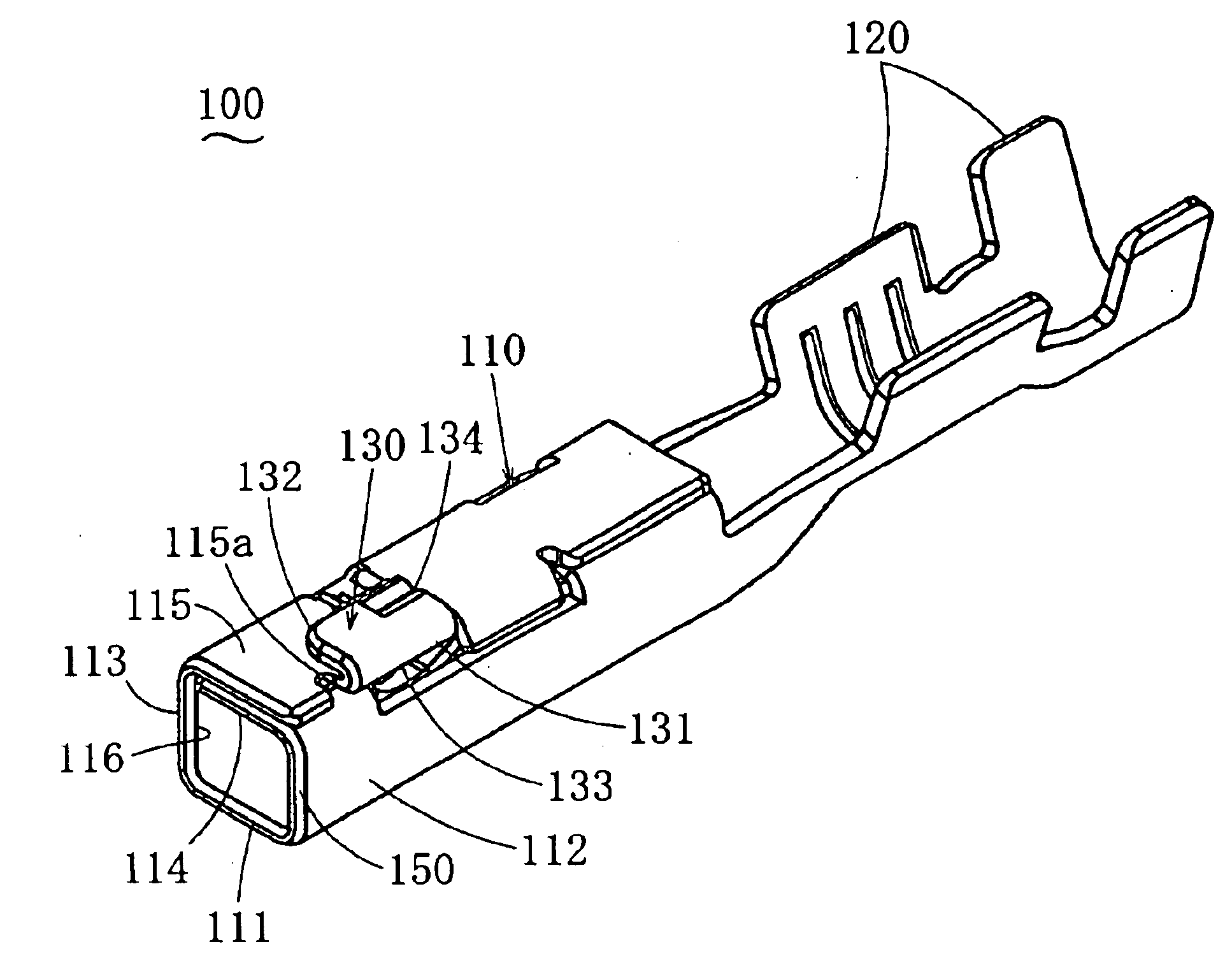
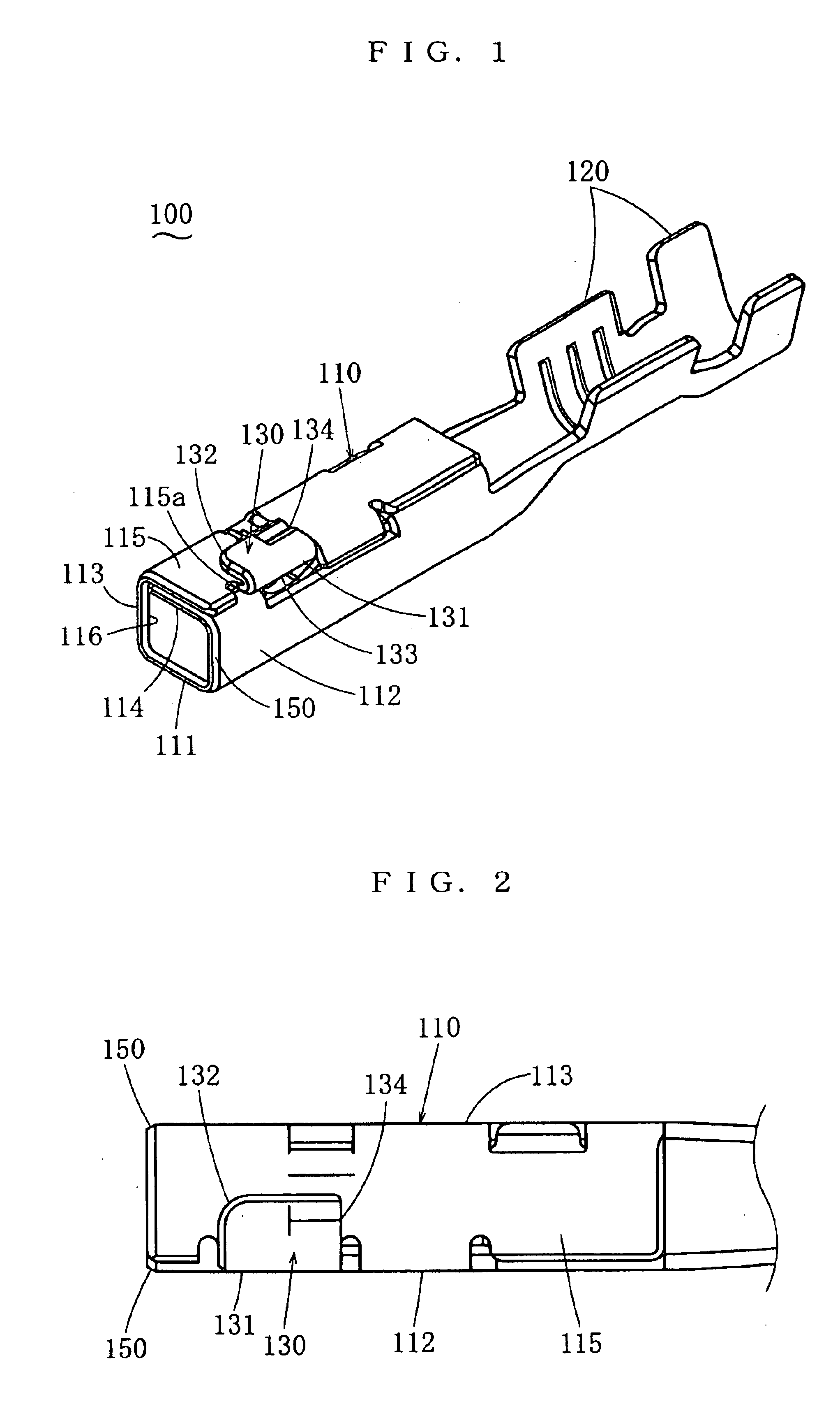
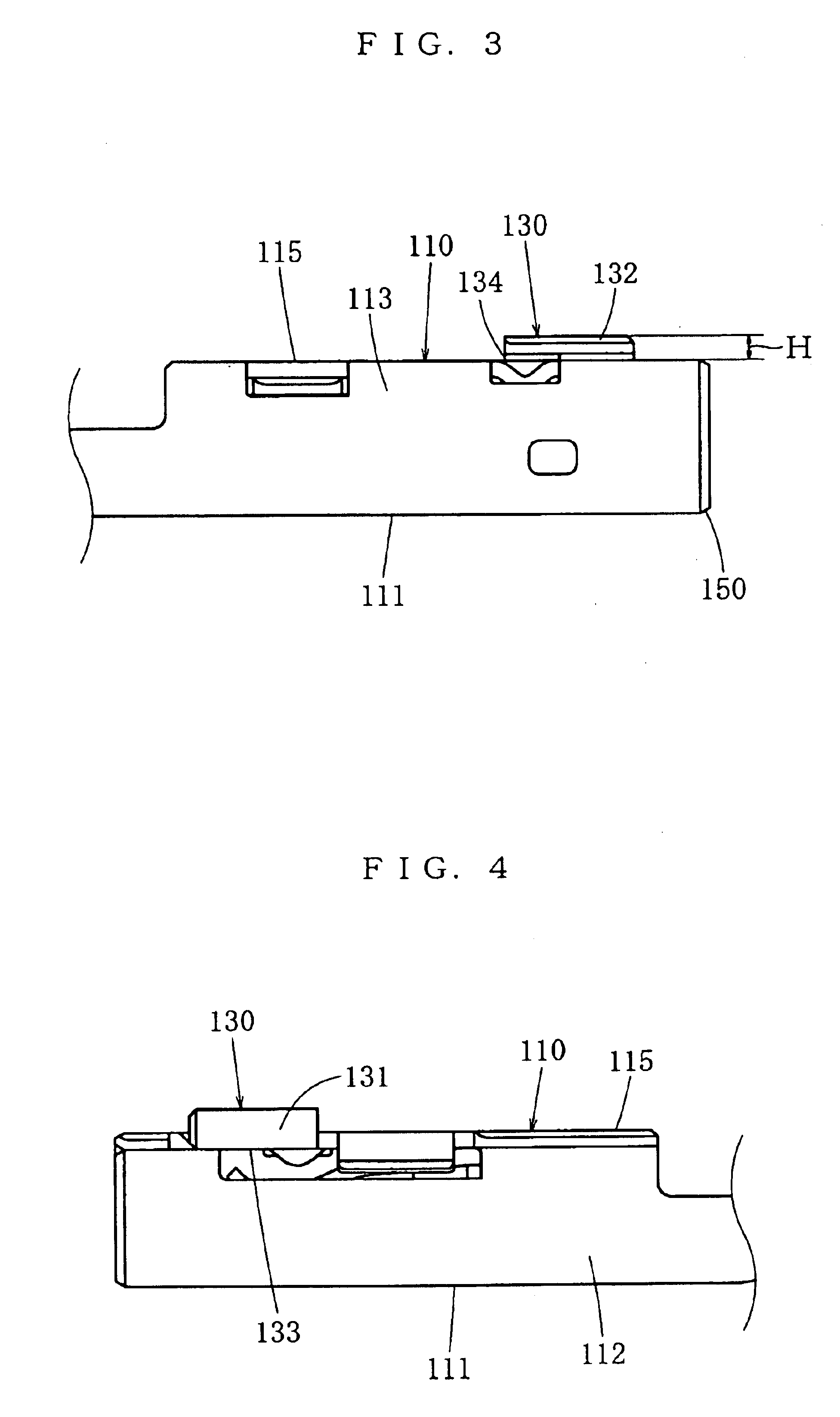
[0031]Some embodiments of the present invention will be described in the following. FIG. 1 through FIG. 6 show a terminal 100 being the first embodiment of the present invention. This terminal 100 is a female-type terminal. This terminal 100 is formed by folding a blank of a certain configuration. This blank is obtained by working such as blanking a thin plate of a certain thickness. As shown in FIG. 7, the terminal 100 is connected to an electric wire W being a conductor, then the terminal 100 is inserted into a receiving cell 210 of a housing 200 having the receiving cells 210 as will be described later and fitted on the housing 200. This completes a nonwaterproof electric connector C1 or a waterproof electric connector C2.

[0032]The terminal 100 is made of a conductive material. The terminal 100 comprises a body 110 to be connected to a counterpart terminal, a connecting part 120 extending from this body 110 rearward in the depth direction and to be connected to the electric wire ...


PUM


Abstract

The objective is to provide a terminal that can be used in waterproof electric connectors without damaging the sealing member thereof and can reliably prevent the body and the spring from being deformed through reducing the load on the body and enhancing the strength of the body. The terminal according to the present invention comprises a rectangular-tube-shaped body being formed of a cross plate, a first vertical plate and a second vertical plate bending from both ends in the width direction of the cross plate and rising to one side in the thickness direction, an inner plate bending from the first vertical plate and extending in the width direction close to the second vertical plate, and an outer plate bending from the second vertical plate and extending in the width direction close to the first vertical plate to overlap with the inner plate, a connecting part extending from the body, and a laid-down protruding piece bending from the end in the width direction of the outer plate of the body to reverse in the width direction, extending in the width direction and having a width equal to or narrower than the width of the outer plate.

Description

BACKGROUND OF THE INVENTION[0001]1. Field of the Invention[0002]This invention belongs to the field of terminals of electric connectors and relates to a terminal having a laid-down protruding piece that exhibits at least one function of a function of guiding the terminal to a predetermined position inside a receiving cell of a housing when the terminal is to be inserted into the receiving cell, a function of being fitted on a flexible piece of the housing and a function of preventing the terminal from being inserted into the housing the other way.[0003]2. Related Art[0004]Japanese Patent Unexamined Publication 2000-231956 discloses a female-type terminal of electric connector. The front half of this female-type terminal is approximately formed into a box shape so that the front half can be inserted into a receiving cell of a housing, a port is opened in the front end thereof for accepting a male-type terminal, a connecting part to be connected with an electric wire is provided in th...

Claims


Application Information

Patent Timeline
Patent Type & Authority Patents(United States)
IPC IPC(8): H01R13/115H01R13/04H01R13/422H01R4/18H01R4/10H01R13/11
CPCH01R13/4223H01R13/113H01R13/04H01R4/185
Inventor CHEN, PING
Owner JST MFG CO LTD
Why Eureka
Try Eureka