Patient compliance monitor

a technology for monitoring monitors and patients, applied in the field of patient compliance monitors, can solve the problems of little guarantee that a patient will follow the prescribed regimen and achieve the desired effect, and the best of medical devices can be rendered ineffective or less than desirable,

Inactive Publication Date: 2005-08-09
BRAVA
View PDF17 Cites 45 Cited by
  • Summary
  • Abstract
  • Description
  • Claims
  • Application Information

AI Technical Summary

Problems solved by technology

A problem which exists universally, and which the inventor herein has encountered with his various inventions, is that of patient compliance.
Even the best of medical devices can be rendered ineffective or produce less than desirable results should the patien...

Method used


Image

  • Patient compliance monitor
  • Patient compliance monitor

Examples


Embodiment Construction

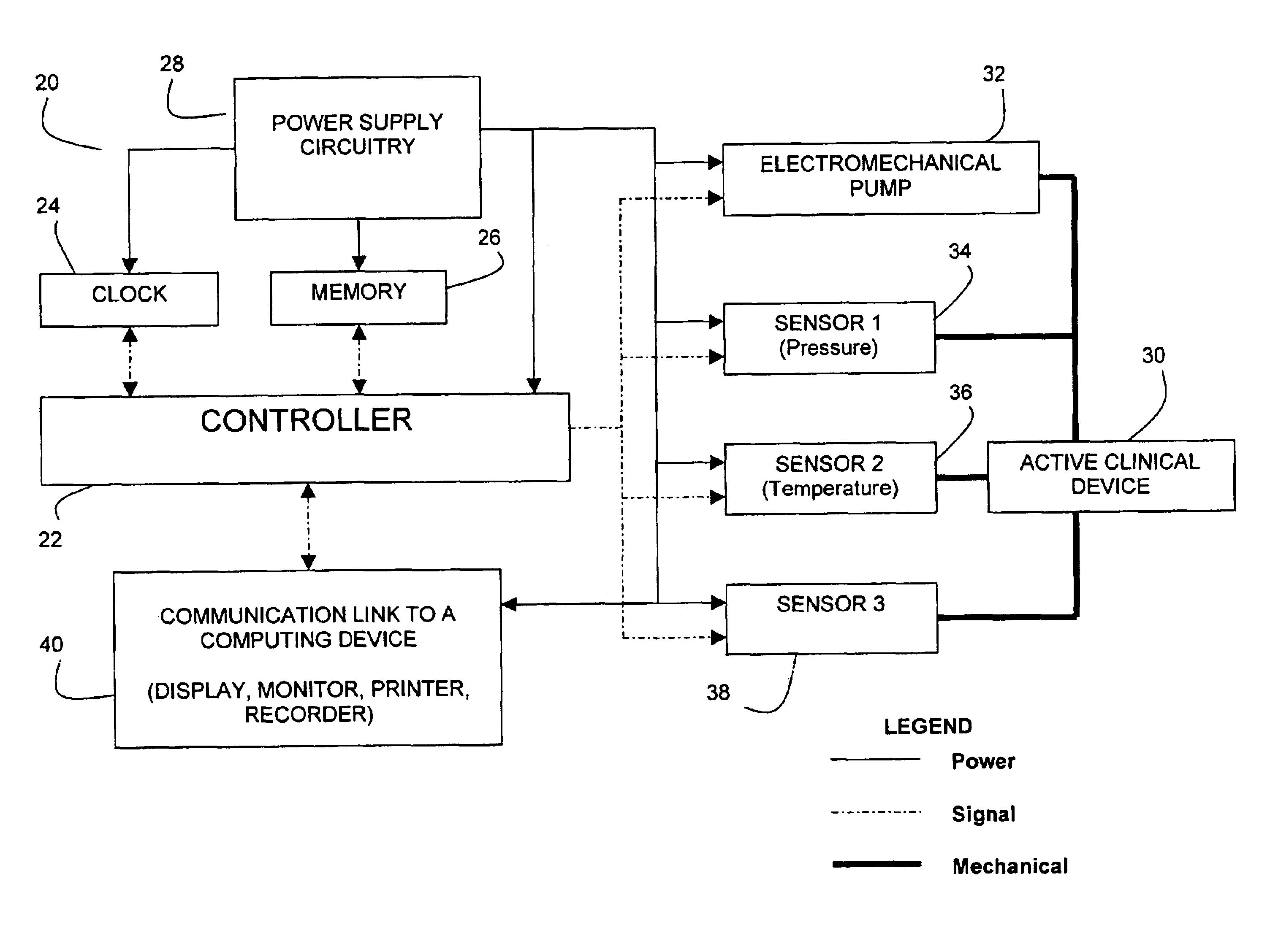
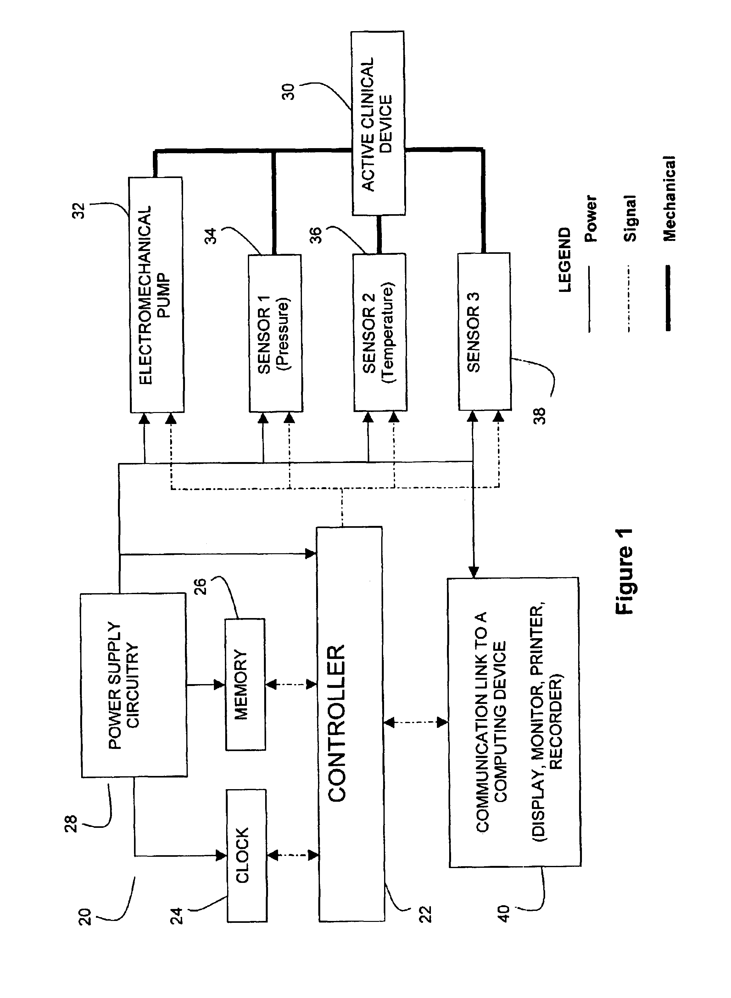
[0009]The patient compliance monitoring device 20 of the present invention is shown in the FIGURE to include a controller 22 which may be a microprocessor, microcomputer, digital logic device, PAL, or other such suitable controller including one as may be embodied in an ASIC, as would be known to those of skill in the art. A clock or timing circuit 24 and memory 26 may be separately provided or provided as part of controller 22 as desired and appropriate under the circumstances of the particular devices chosen to embody these functions. However, this is considered to be a matter of design choice and not significant with respect to the operation or best mode choice for the present invention. Similarly, a power supply circuit 28 is shown and may include a battery with wave form smoothing or filtering again as would be known to those of skill in the art. The active clinical device 30 may be considered as a soft tissue enlargement device as shown in any of the inventor's prior patent fi...


PUM


Abstract

A patient monitoring device includes a microprocessor controller having a clock circuit and memory coupled to one or more sensors physically carried by a medical appliance such that as the medical appliance is properly fitted to and worn by the patient, the sensors provide an electrical signal confirming that which may be then timed to provide data which confirms a patient's compliance with a recommended protocol. By combining and correlating the sensor data with the clock or timer provided as part of the controller, a time chart of data may be created indicating when and for how long the patient actually wears the device. Additionally, other sensors may be used to collect data relating to various operational parameters of the device including the amount of negative pressure presented under a vacuum dome or other parameters related to the operation of the medical appliance itself, as desired.

Description

CROSS REFERENCE TO RELATED APPLICATIONS AND PATENTS[0001]This is a continuation of U.S. patent application Ser. No. 09 / 572,348, filed May 17, 2000, now U.S. Pat. No. 6,514,200, which issued Feb. 4, 2003, the entire disclosure of which is incorporated herein by reference.[0002]Further, this application is related to, but does not claim priority from, the following related applications and patents naming the inventor as an inventor thereof: U.S. Pat. No. 5,536,233; U.S. Pat. No. 5,662,583; U.S. Pat. No. 5,676,634; U.S. Pat. No. 5,695,445; U.S. Pat. No. 5,701,917; U.S. patent application Ser. No. 09 / 203,832 and U.S. patent application Ser. No. 09 / 141,460; the disclosures of which are incorporated herein by reference.BACKGROUND OF THE INVENTION[0003]There are numerous instances where persons desire enlargement of the soft tissue in their bodies. The inventor herein has worked extensively in this area by inventing and patenting various devices and methods for growing and enlarging soft t...

Claims


Application Information

Patent Timeline
IPC IPC(8): A61H9/00G06F19/00A61B5/00G16H20/30G16H40/67
CPCA61H9/005G06F19/322G06F19/3481G06F19/3487A61B5/0002A61H2205/081A61H2230/00Y10S128/92G16H10/60G16H15/00G16H40/67G16H20/30
Inventor KHOURI, ROGER K.
Owner BRAVA
Why Eureka
Try Eureka