Umbrella device

a technology for umbrellas and covers, applied in umbrellas, walking sticks, umbrellas, etc., can solve the problems of prone to buckling, low flexural strength of thin cover materials, strain caused by rod folding up, etc., and achieve the effect of reducing the risk of damage to the thin cover material of low flexural strength at the contact point between the cover and the cover

Inactive Publication Date: 2005-09-13
TRANSSOLAR ENERGIETECHN +1
View PDF21 Cites 16 Cited by
  • Summary
  • Abstract
  • Description
  • Claims
  • Application Information

AI Technical Summary

Benefits of technology

[0005]It is the object of the present invention to provide an umbrella device of the type mentioned at the outset which, while avoiding the above mentioned disadvantages, can be opened up and folded again in a simpler, and in particular automatic way.
[0007]A light-weight umbrella device which can be automatically opened up is created by means of the steps in accordance with the present invention, which can be mechanically simplified and can be produced with a large area in particular. The umbrella device moreover provides an active ventilation of the space underneath the umbrella-like cap.
[0010]The membrane can have a pagoda-shaped cut-out shape, matched to the specific influencing variables suitably employed for improving the aerodynamic stability of the umbrella device. For example, a shape of the cap can include ballast which can be useful.
[0011]Providing the membrane with radially and / or annularly arranged cords is also advantageous for improving the aerodynamic stability of the umbrella device. Favorable embodiments thereof ensue from a membrane provided with additional masses on the outer circumference of the membrane, such as a cord at the edge, individual weights, doubling of the membrane, or the like.
[0012]A further option for improving the aerodynamic stability and / or the unfolding process of the umbrella-like cap of the umbrella device results, from a membrane having a flat, pillow-like shape, which may be divided into radially and / or annularly arranged air chambers connected with a blower, or a pneumatic drive, from having the inside of the membrane, which is at rest, charged with compressed air, and from providing the shank with outlet openings in the area of the membrane when at rest.

Problems solved by technology

With a filigreed weight-reducing design they are prone to buckling when strained by wind.
The controlled folding up of the cover material and of the rod produces strain has been shown to be technically difficult with umbrella devices of large surface areas, and poses the danger of damage to the thin cover material of low flexural strength in the contact points between the cover and the ribs.
Such umbrella devices with a manually rotatable cap are relatively expensive to produce and elaborate in use, since they can be opened up-only over provided ribs, which moreover have a considerable weight.

Method used


Image

  • Umbrella device
  • Umbrella device
  • Umbrella device

Examples


Embodiment Construction

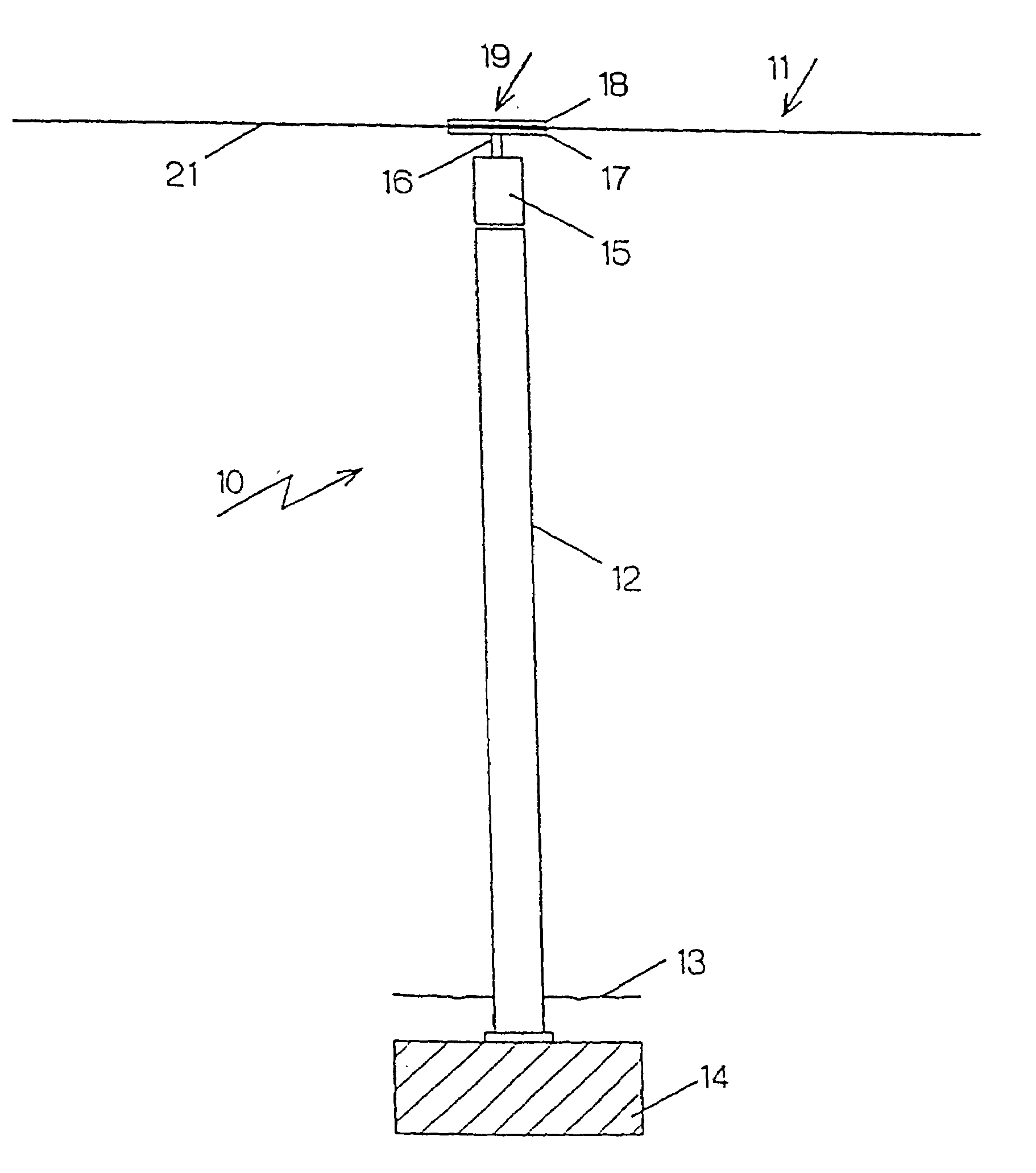
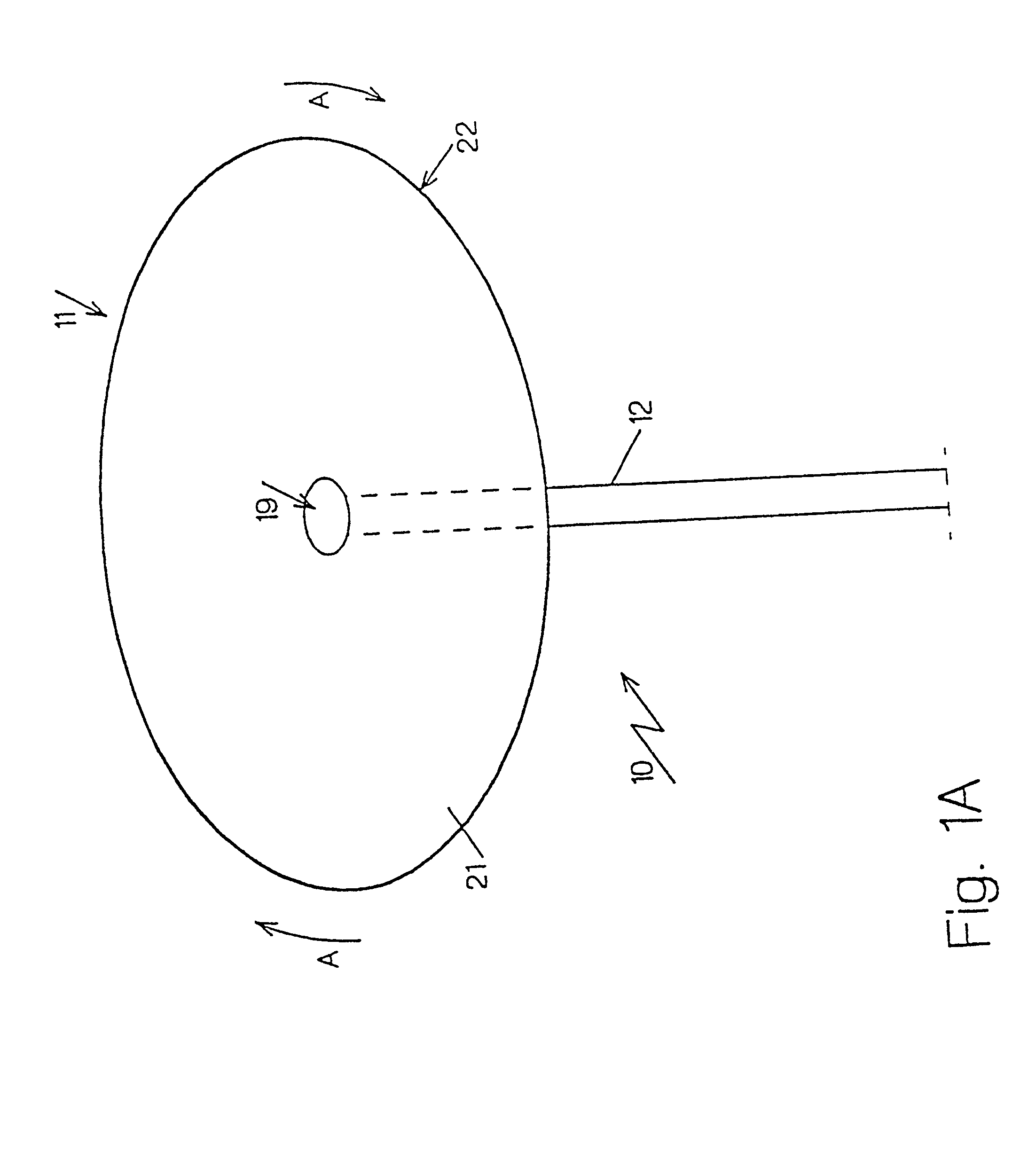
[0021]The umbrella device 10, 110 or 210 represented in the drawings has a ribless, umbrella-like cap 11, 111 or 211, which is rotatably maintained at the upper end of a shank 12, 112 or 212 and can be rotatably driven in such a way, that the umbrella-like cap 11 can be opened-up from a drooping, limp position of rest into an umbrella-like operating position, can be maintained opened up and stabilized by the centrifugal force resulting from its rotation.

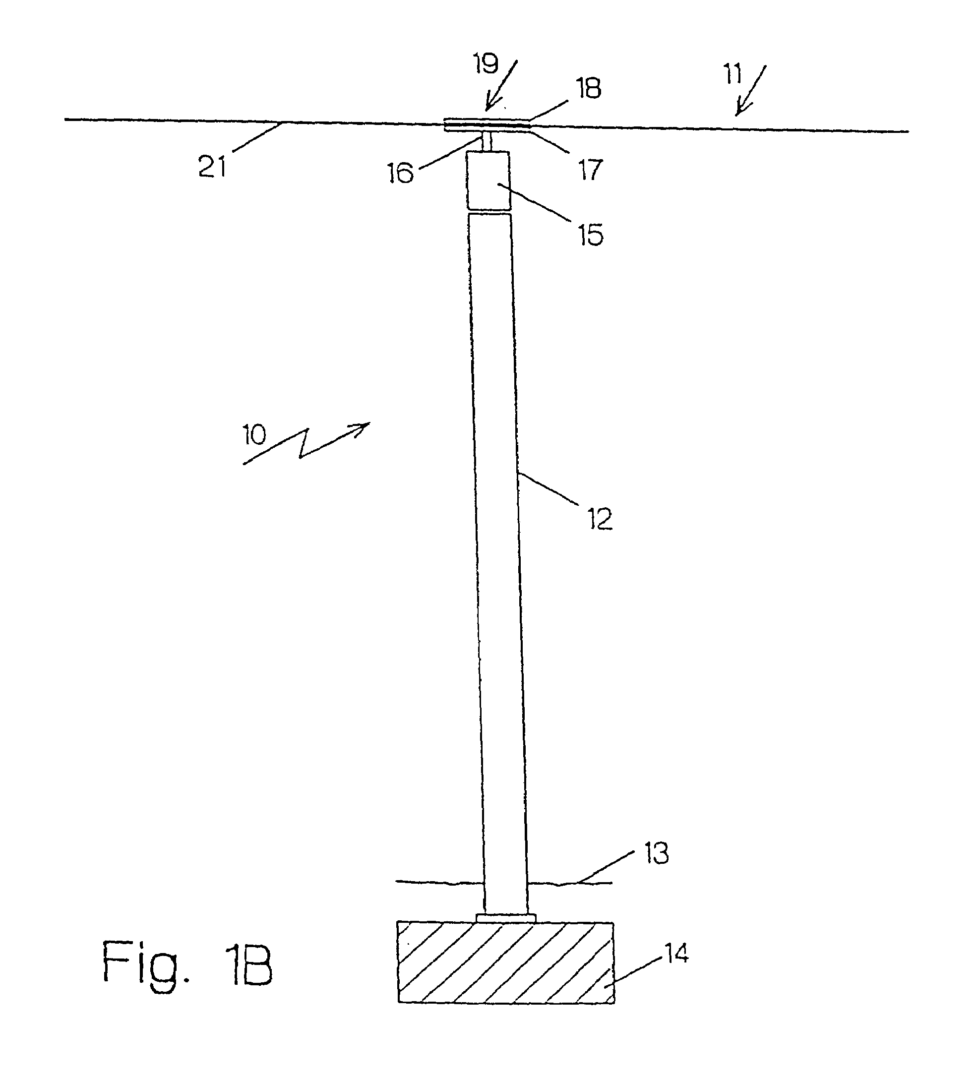
[0022]In accordance with FIG. 1B, the upwardly extending shank 12 is maintained fixed in place, for example fastened underneath the bottom-surface 13 on a block 14. A motor drive 15 is fastened or flanged at the upper end of the shank 12, whose vertically upwardly projecting drive shaft 16 is connected, fixed against relative rotation, with a lower disk 17 which, together with an oppositely located upper disk 18 is a part of a fastening device 19 for the cap 11.

[0023]The umbrella-like cap 11 essentially consists of a membrane 21 made...


PUM


Abstract

An umbrella device which has a shank, an umbrella-like cap formed as a membrane and a driver. The membrane is connected to the shank and is caused by the driver to move from a position of rest where it droops limply around the shank to an open position where it is essentially horizontal due to the centrifugal forces of the membrane produced by the rotation of the membrane by the driver.

Description

FIELD OF THE INVENTION[0001]The present invention relates to an umbrella device having a shank and an umbrella-like cap which can rotate around the shank and opened up.BACKGROUND OF THE INVENTION[0002]Umbrella devices in the form of umbrellas and parasols are known, whose umbrella-like cap is provided with ribs, one end of which is linked to a ring arranged at the upper end of a shank and the other end at a sleeve, which can be displaced and fixed in place along the shank for spreading the umbrella cap.[0003]These ribs are required for supporting the cover material used as the covering. In case of umbrella devices of larger dimension, the ribs already constitute a large proportion of the dead weight of the umbrella device. With a filigreed weight-reducing design they are prone to buckling when strained by wind. The controlled folding up of the cover material and of the rod produces strain has been shown to be technically difficult with umbrella devices of large surface areas, and po...

Claims


Application Information

Patent Timeline
Patent Type & Authority Patents(United States)
IPC IPC(8): A45B23/00A45B19/00A45B19/02
CPCA45B19/02A45B23/00A45B2023/0012A45B2023/0093
Inventor SOBEK, WERNERSCHULER, MATHIASBAUMULLER, DOMINIK
Owner TRANSSOLAR ENERGIETECHN
Why Eureka
Try Eureka