Magnetic head heating element in a disk drive

a heating element and disk drive technology, applied in the direction of mounting the head within the housing, maintaining the alignment of the head carrier, instruments, etc., can solve the problems of shortening the lifetime of the magnetic disk device, and affecting the operation of the disk driv

Inactive Publication Date: 2005-11-08
HITACHI GLOBAL STORAGE TECH JAPAN LTD +1
View PDF12 Cites 67 Cited by
  • Summary
  • Abstract
  • Description
  • Claims
  • Application Information

AI Technical Summary

Problems solved by technology

When the protective film on the surface of the head element wears due to collision with small protrusions on a surface of the magnetic disk, the head element cannot be protected and damage such as corrosion is more likely to occur, resulting in shorter lifetime of the magnetic disk device.
Hence, the element is more likely to collide with the small protrusions on the surface of the magnetic disk, resulting in an abnormal signal due to damage on the element and thermal asperity.
), a distance (magnetic spacing) between the head element and a magnetic medium is increased when the slider flies, resulting in inability to perform recording and reading.

Method used


Image

  • Magnetic head heating element in a disk drive
  • Magnetic head heating element in a disk drive
  • Magnetic head heating element in a disk drive

Examples


embodiment 1

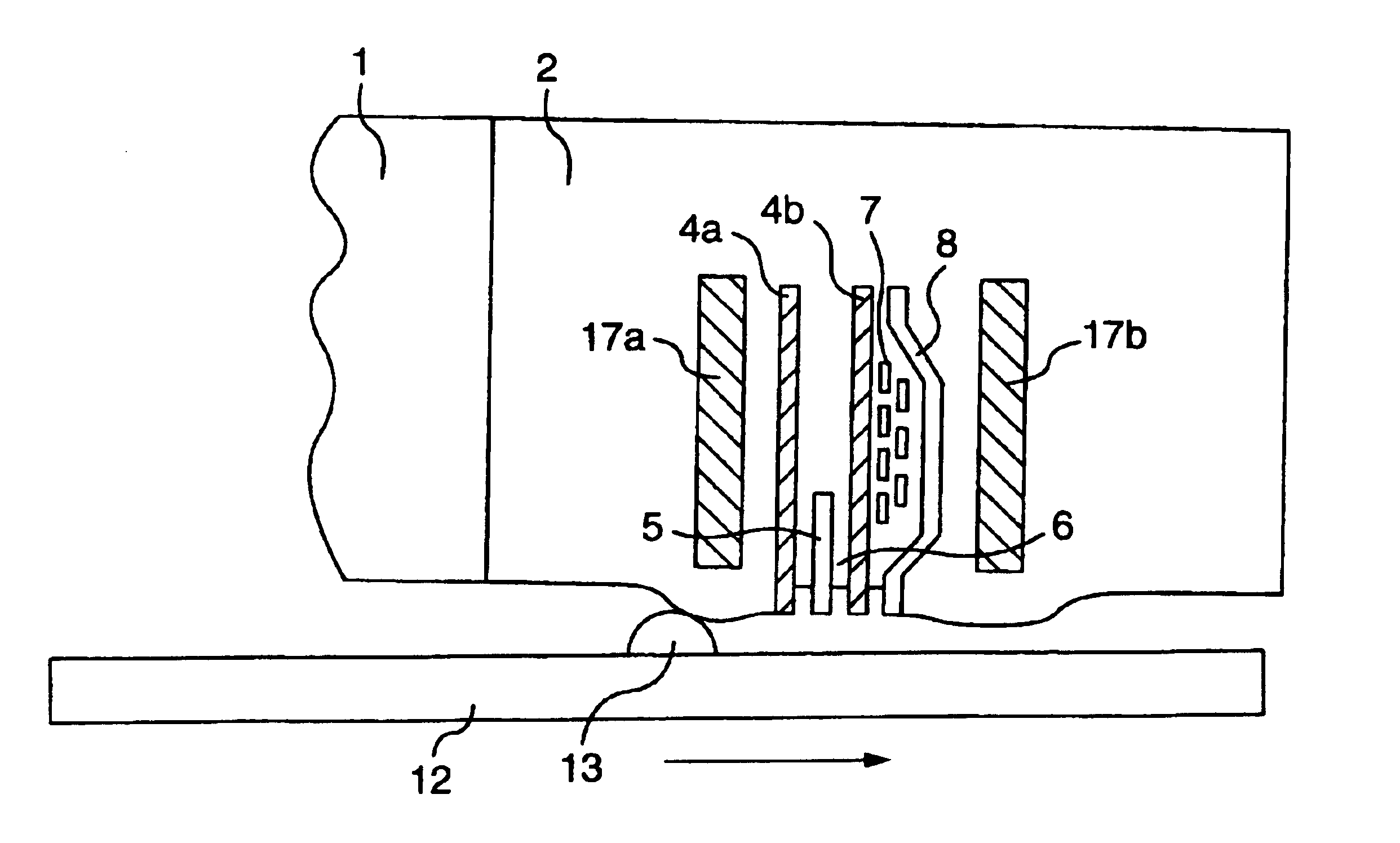
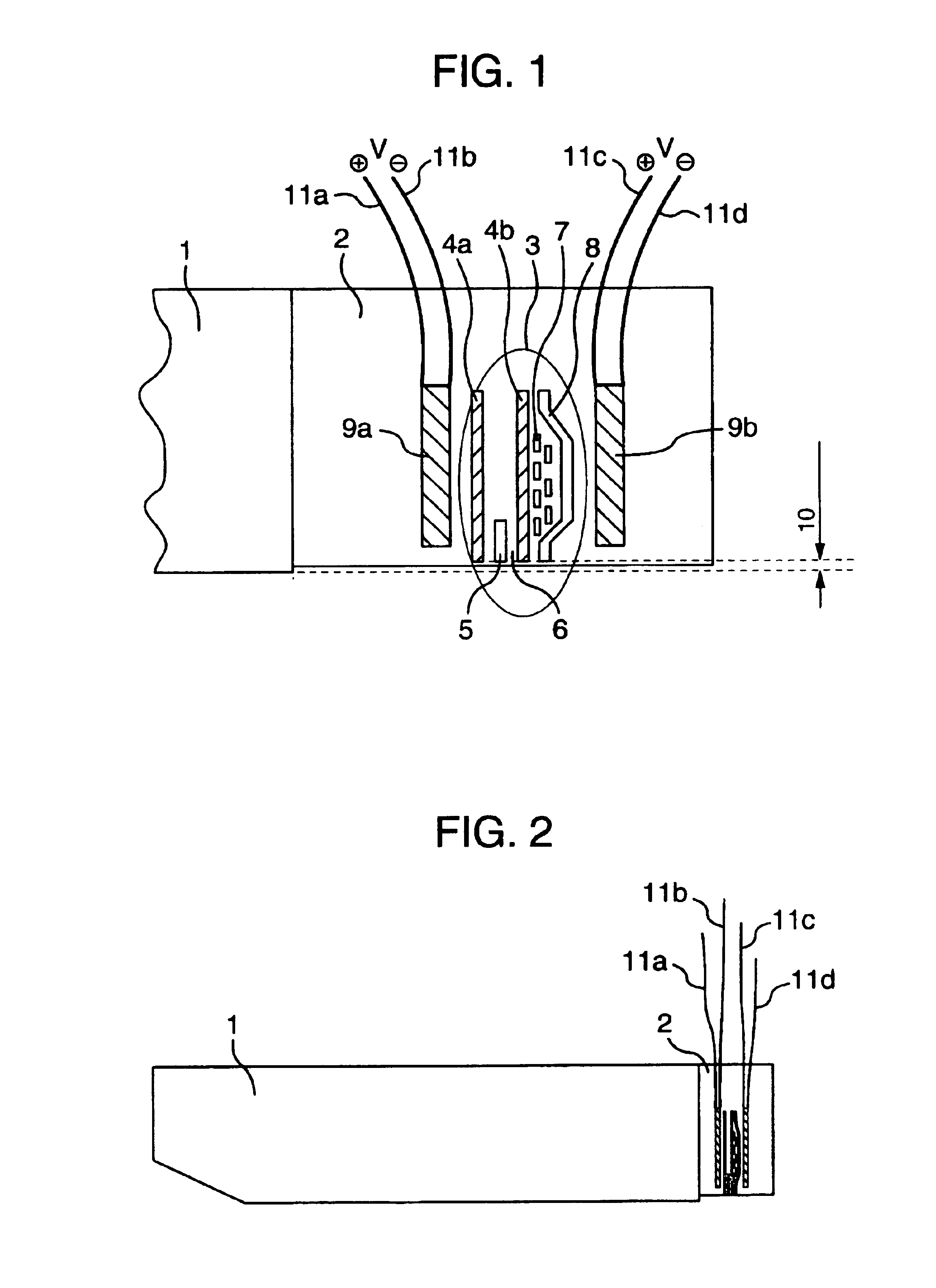
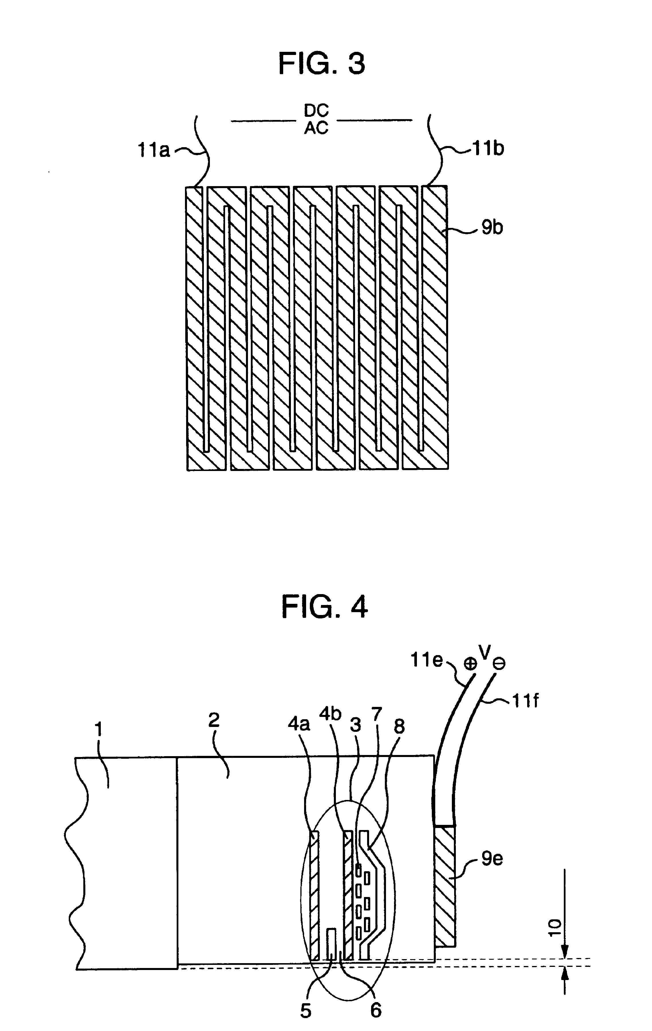
[0037]The following will discuss embodiments of the present invention referring to the drawings. Referring to FIGS. 1 to 4, Embodiment 1 of a magnetic head slider according to the present invention will be discussed by taking a magnetoresistance type head as an example. FIG. 1 is an enlarged side view showing a magnetic head, and FIG. 2 is a side view showing the magnetic head slider.

[0038]Further, FIG. 22 schematically shows the configuration of a magnetic disk device according to the present invention. FIG. 22 is a perspective view showing a magnetic head device 100 having a magnetic head slider 104, which will be discussed below.

[0039]In a magnetic disk device 101, a hub 103 is driven and rotated around a rotary axis 102 by a spindle motor (not shown). A plurality of rotating magnetic disks 101 is attached to the hub 103 inside a casing (case) 111. The slider 104 positioned on a surface of the disk floats via a small gap due to the rotation of the magnetic disk 101 and is support...

embodiment 2

[0057]Referring to FIGS. 10 to 12, a magnetic head slider of the present invention will be discussed. FIG. 10 is a side view showing a magnetic head part having a temperature sensor bonded to the rear of the head. FIG. 11 is a side view showing the magnetic head part having a temperature sensor bonded to the back of the head. FIG. 12 is a drawing taken from the back of the magnetic head part having temperature sensors bonded to the side of the head.

[0058]The configuration of the present embodiment will be discussed. According to the present embodiment, in the configuration of Embodiment 1 of the present invention, a temperature sensor 14a is further provided on the rear of the magnetic head and a control circuit 15 is provided which uses the temperature sensor to control voltage or current applied to the electric conducting films so as to control a temperature of the head element part 3.

[0059]Besides, in the present embodiment, as shown in FIG. 11, a temperature sensor 14b may be p...

embodiment 3

[0061]Referring to FIGS. 13 and 14, a magnetic head slider of the present invention will he discussed. FIG. 13 is a side view showing the magnetic head part having electric conducting films connected to a load / unload (L / UL) control circuit. FIG. 14 is a flowchart showing load / unload control.

[0062]The configuration of the present embodiment will be discussed below. The present embodiment is identical to Embodiment 1 of the present invention in configuration of a head. The head is configured such that the head element 3 has a machining step (PTR) when current is not applied to the head element 3 or the electric conducting films 9a and 9b. Further, the present embodiment has the load / unload mechanism, and application of voltage or current to the electric conducting films is controlled by an operation command of load / unload control of the magnetic head slider 1. To be specific, a control circuit 16 is provided which reduces voltage or current applied to the electric conducting films 9a...


PUM

PropertyMeasurementUnit
flying heightaaaaaaaaaa
temperatureaaaaaaaaaa
lengthaaaaaaaaaa

Abstract

An object of the present invention is to prevent a spacing between a magnetic head and a writing medium at low temperature from increasing to cause a writing/reading error, and to prevent the magnetic head element protruded by a temperature increase from colliding with small protrusions on a magnetic disk surface, and to prevent damage on the element, and to prevent the occurrence of thermal asperity. In order to attain the object, a magnetic head slider is provided, which includes a magnetic head element supported on a rotating magnetic disk via a gap to write or read information on the magnetic disk, and a heat source for heating the magnetic head element. A magnetic disk device is further provided, which includes a magnetic head slider.

Description

TECHNICAL FIELD[0001]The present invention relates to a floating type or sliding type magnetic head slider having a magnetic head for reading and writing information on a magnetic disk, and a magnetic disk device including the magnetic head slider.BACKGROUND ART[0002]In order to respond to the need for higher recording density of a magnetic disk device, it has been more necessary to reduce a flying height of a magnetic head slider (simply referred to it as a slider) in recent years. Meanwhile, the smaller a flying height of a slider, R / W (Read / Write) elements are more prone to collide with small protrusions, which are resulted from a rough surface of a magnetic disk. In recent years, a slider has had a small flying height of 30 nm or less relative to a magnetic disk, so that the probability of collision has increased between small protrusions on a surface of a magnetic disk and a magnetic head element (simply referred to it as a head element). In the case of a magnetoresistance effe...

Claims


Application Information

Patent Timeline
Patent Type & Authority Patents(United States)
IPC IPC(8): G11B5/105G11B5/10G11B5/54G11B5/56G11B5/012G11B5/58G11B5/40G11B5/60G11B5/00G11B5/48
CPCG11B5/012G11B5/105G11B5/40G11B5/54G11B5/56G11B5/58G11B5/581G11B5/6005G11B5/488G11B2005/0013G11B5/607G11B5/5565
Inventor XU, JUNGUOTSUCHIYAMA, RYUJITOKUYAMA, MIKIOMATSUMOTO, MASAAKI
Owner HITACHI GLOBAL STORAGE TECH JAPAN LTD
Why Eureka
Try Eureka