Foldable keyboard

a keyboard and folding technology, applied in the field of folding keyboards, can solve the problems of unstable folding and opening motion of the keyboard unit, and deterioration of the keyboard appearan

a keyboard and folding technology, applied in the field of folding keyboards, can solve the problems of unstable folding and opening motion of the keyboard unit, and deterioration of the keyboard appearan

US6991389B2Active Publication Date: 2006-01-31BROTHER KOGYO KK

Image

  • Foldable keyboard
  • Foldable keyboard
  • Foldable keyboard

Examples


Embodiment Construction

[0068]A detailed description of a preferred embodiment of a foldable keyboard embodying the present invention will now be given referring to the accompanying drawings.

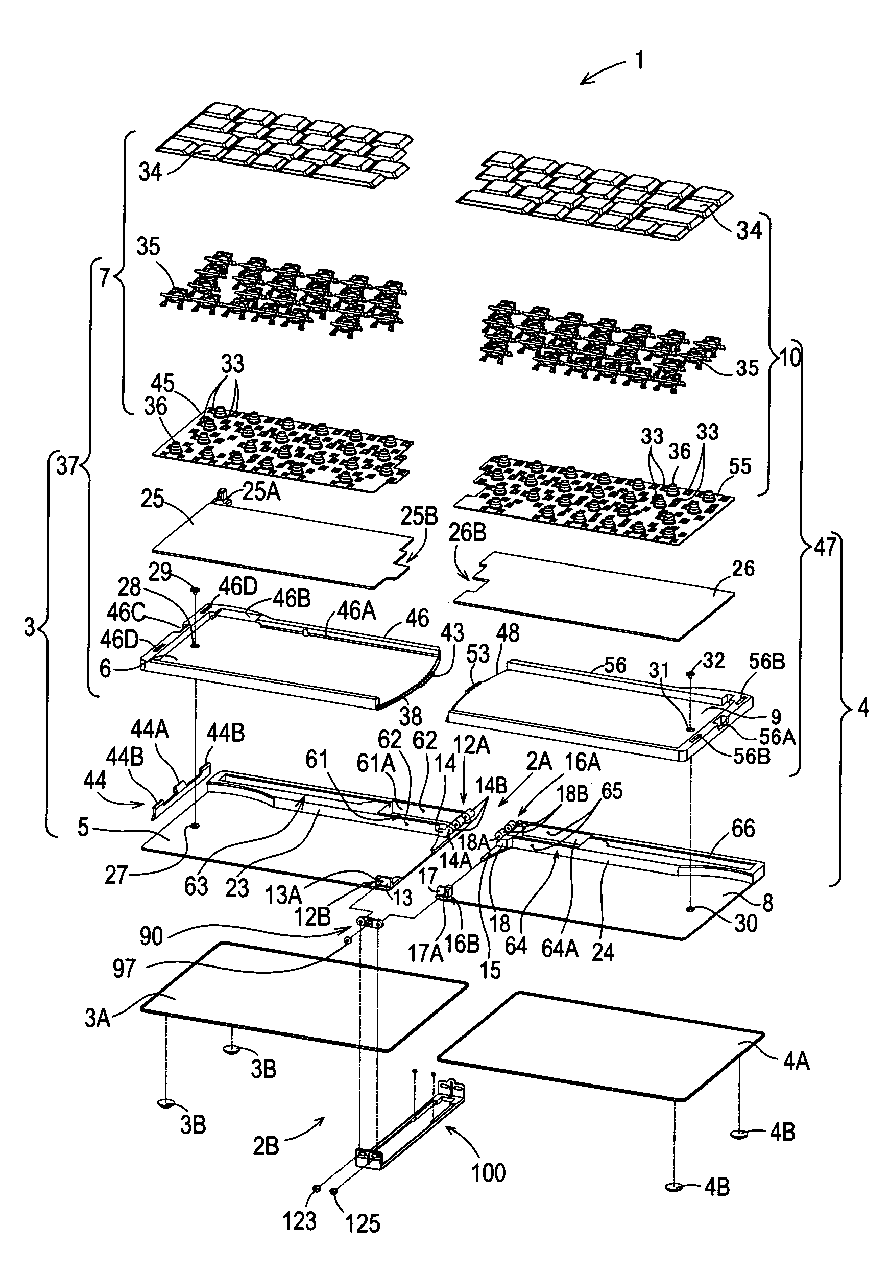
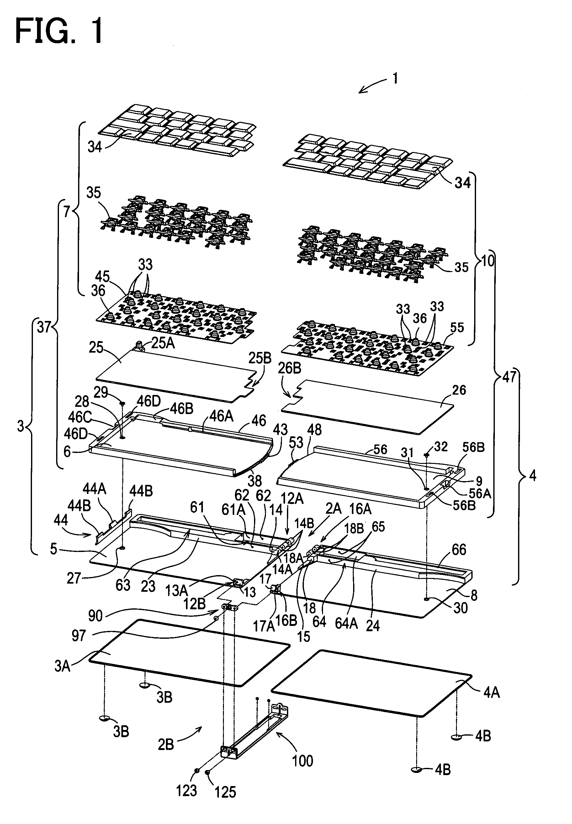
[0069]First, the structure of the keyboard in the present embodiment is explained with reference to FIGS. 1 and 2. FIG. 1 is an exploded perspective view of the keyboard, seen from the front; and FIG. 2 is an exploded perspective view of the keyboard, seen from the back.

[0070]In FIGS. 1 and 2, a keyboard 1 is mainly constructed of a first keyboard unit 3 and a second keyboard unit 4 which are rotatably connected with each other through a first rotational connecting part 2A (at the back side in FIGS. 1 and 2) and a second rotational connecting part 2B (at the front side in FIGS. 1 and 2). The first keyboard unit 3 includes a first surface plate 3A attached with two rubber support legs 3B in two outer corners, a first base plate 5, a first support plate 6 mounted to be horizontally turnable on the first base plate 5, and...


PUM


Abstract

In a foldable keyboard, a cover member (100) includes a cover part (101) provided with a cover plate (104) and a pair of supporting elements (102, 103) formed on both ends of the cover plat. The supporting elements are each formed with a first slot (117) and a second slot (118). A support screw (123) passes with play through the first slot and is fixedly received in a baring hole (13A) of a bearing member (13) formed in a corner (12B) of a first keyboard unit (3) and a support screw (124) passes with play through the first slot and is fixedly received in a support hole (121) of a first base plate (5) formed in a corner (12A). A support screw (125) passes with play through the second slot and is fixedly received in a bearing hole (17A) of a bearing member (17) formed in a corner (16B) of a second keyboard unit (4) and a support screw (126) passes with play through the second slot and is fixedly received in a support hole (120) of a second base plate (8) formed in a corner (16A).

Description

BACKGROUND OF THE INVENTION[0001]1. Field of the Invention[0002]The present invention relates to a foldable keyboard with superior portability and good operationality in use and, more particularly, to a foldable keyboard including two keyboard units and a cover member which is turned in synchronization with rotation of each keyboard unit and covers end faces and both side portions of each end face of the keyboard units held in a superposed state.[0003]2. Description of Related Art[0004]Heretofore, there have been proposed various types of foldable keyboards including two separate keyboard units rotatably connected with each other. When the keyboard is not in use, the keyboard units are superposed one on top of the other to bring the keyboard into a folded compact state, thus making it easy to carry anywhere. When in use, on the other hand, the keyboard units are separated to unfold the keyboard into a spread state, thus providing high operationality equivalent to standard keyboards....

Claims


Application Information

Patent Timeline
31 Jan 2006
Publication
US6991389B2
IPC
B41J5/08; B41J5/10; B41J5/12; H01H13/70
CPC
H01H13/70; H01H2223/052; H01H2223/05
Inventors
MOCHIZUKI, ISAO; TAKAGI, TAKEYUKI