Locking bolt work apparatus for automated banking machine

a technology of locking bolts and work apparatuses, which is applied in the direction of automatic teller machines, atm details, instruments, etc., can solve the problems of increasing the cost of automated banking machines, increasing the difficulty of authorized personnel accessing the secure enclosure, and high complexity of providing enhanced security

Active Publication Date: 2006-02-21
DIEBOLD SELF SERVICE SYST DIV OF DIEBOLD NIXDORF INC
View PDF9 Cites 29 Cited by
  • Summary
  • Abstract
  • Description
  • Claims
  • Application Information

AI Technical Summary

Benefits of technology

[0009]Thus there exists a need for a secure enclosure and a method of manufacturing a secure enclosure for an automated banking machine that is more reliable and economical.
[0010]There also exists a need for a locking bolt work apparatus for a door of an automated banking machine that provides enhanced security, but which is also economical with low complexity and which can be quickly opened by authorized personnel. There also exists the need for a method of assembling the locking bolt work apparatus to a secure enclosure that can be readily accomplished in a more efficient manner.

Problems solved by technology

However, providing enhanced security also often comes with a high degree of complexity.
This increases the cost of the automated banking machine.
Complex mechanisms can also make it more difficult for authorized personnel to gain access to the secure enclosure.

Method used


Image

  • Locking bolt work apparatus for automated banking machine
  • Locking bolt work apparatus for automated banking machine
  • Locking bolt work apparatus for automated banking machine

Examples


Embodiment Construction

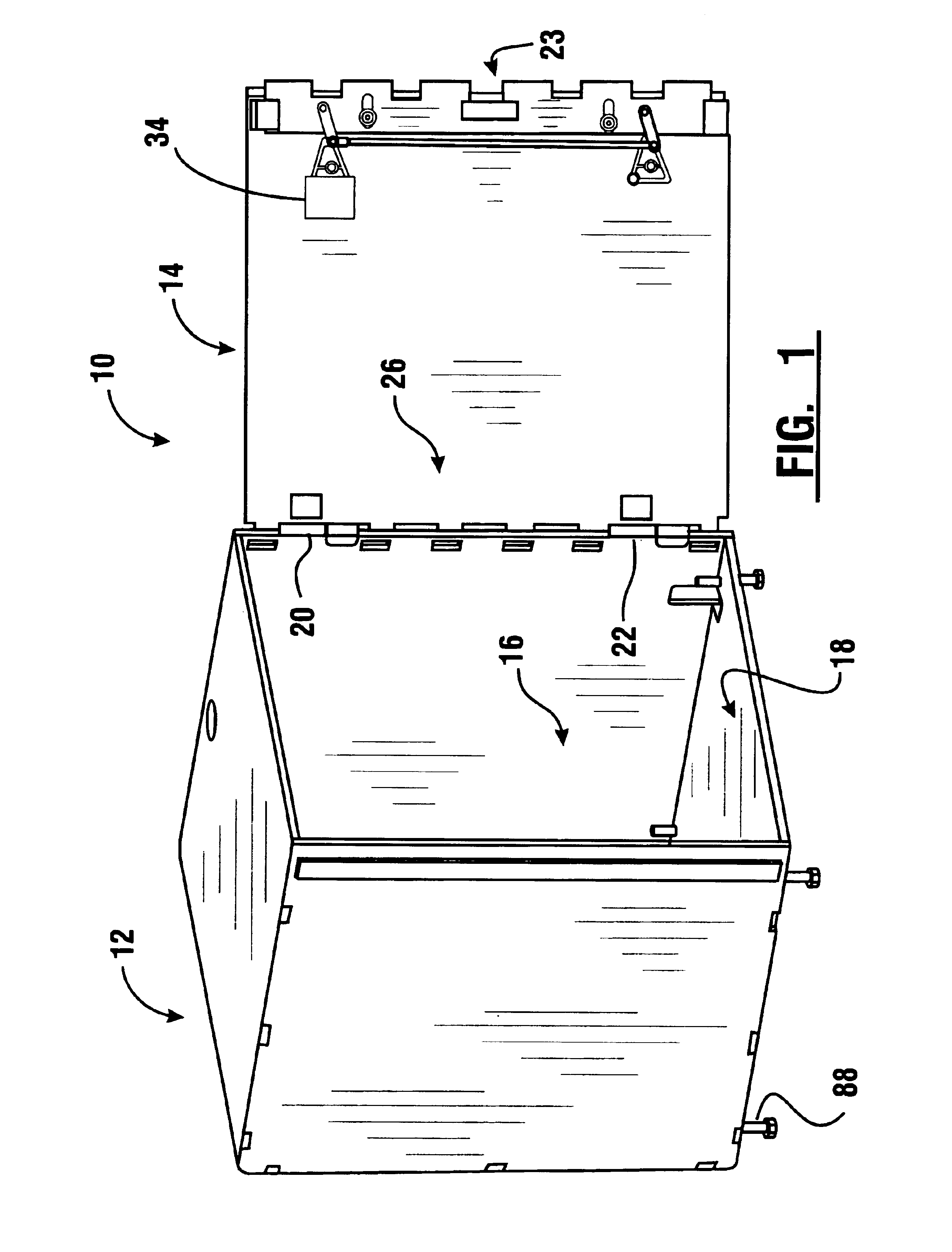
[0069]Referring now to the drawings and particularly to FIG. 1, there is shown therein a secure enclosure arrangement for an automated banking machine of an exemplary embodiment of the present invention, generally indicated 10. It should be understood that the secure enclosure can be part of a larger automated banking machine, such as an ATM or similar apparatus.

[0070]The secure enclosure 10 can include a chest portion and a door. An example of an arrangement of a chest portion and a door for a secure enclosure of an automated banking machine and the assembly thereof may be found in U.S. Pat. No. 6,089,168, the disclosure of which is incorporated herein by reference in its entirety.

[0071]An example of an automated banking machine including a user interface with an opening through which the machine can receive a stack of sheets including currency notes and checks may be found in U.S. Pat. No. 6,749,111, the disclosure of which is incorporated herein by reference in its entirety.

[0072...


PUM


Abstract

A secure enclosure for an automated banking machine includes a chest portion and a moveable door. The door has mounted thereon a locking bolt work mechanism which is operable to secure the door in a closed position. The bolt work mechanism includes a drive cam that is connected to an idler cam by a cam link. The drive cam is further connected to a locking bolt by a drive bolt link. The idler cam is connected to the locking bolt by an idler bolt link. Movement of the drive cam enables movement of the locking bolt between extended and retracted positions. The locking bolt can have a stepped edge configuration to provide stepped engagement in securing a door having a similar stepped edge configuration.

Description

CROSS REFERENCE TO RELATED APPLICATION[0001]This application claims the benefit of U.S. Provisional Application No. 60 / 494,614 filed Aug. 11, 2003.TECHNICAL FIELD[0002]This invention relates to automated banking machines. Specifically this invention relates to a locking bolt work apparatus for a secure enclosure of an automated banking machine, and its method of assembly.BACKGROUND ART[0003]Automated banking machines are known in the prior art. Popular automated banking machines often used by consumers are automated teller machines (ATMs). ATMs are increasingly used by consumers to conduct banking transactions. Common banking transactions conducted by consumers at ATMs include deposits, withdrawals, account transfers, and balance inquiries.[0004]Most ATMs include a secure enclosure. The secure enclosure is used to hold currency and other valuable items inside the machine. Deposits made by customers into an ATM are also preferably held within a secure enclosure until they can be remo...

Claims


Application Information

Patent Timeline
Patent Type & Authority Patents(United States)
IPC IPC(8): E05G7/00E05B65/00E05C19/00G07F19/00
CPCE05B65/0075G07F19/205G07F19/20E05C19/001
Inventor MERCER, SCOTT A.MCCRACKEN, RICHARD W.
Owner DIEBOLD SELF SERVICE SYST DIV OF DIEBOLD NIXDORF INC
Why Eureka
Try Eureka