

Armature of rotating electric machine
- Summary
- Abstract
- Description
- Claims
- Application Information
AI Technical Summary
Benefits of technology
Problems solved by technology
Method used
Image



Examples
first embodiment
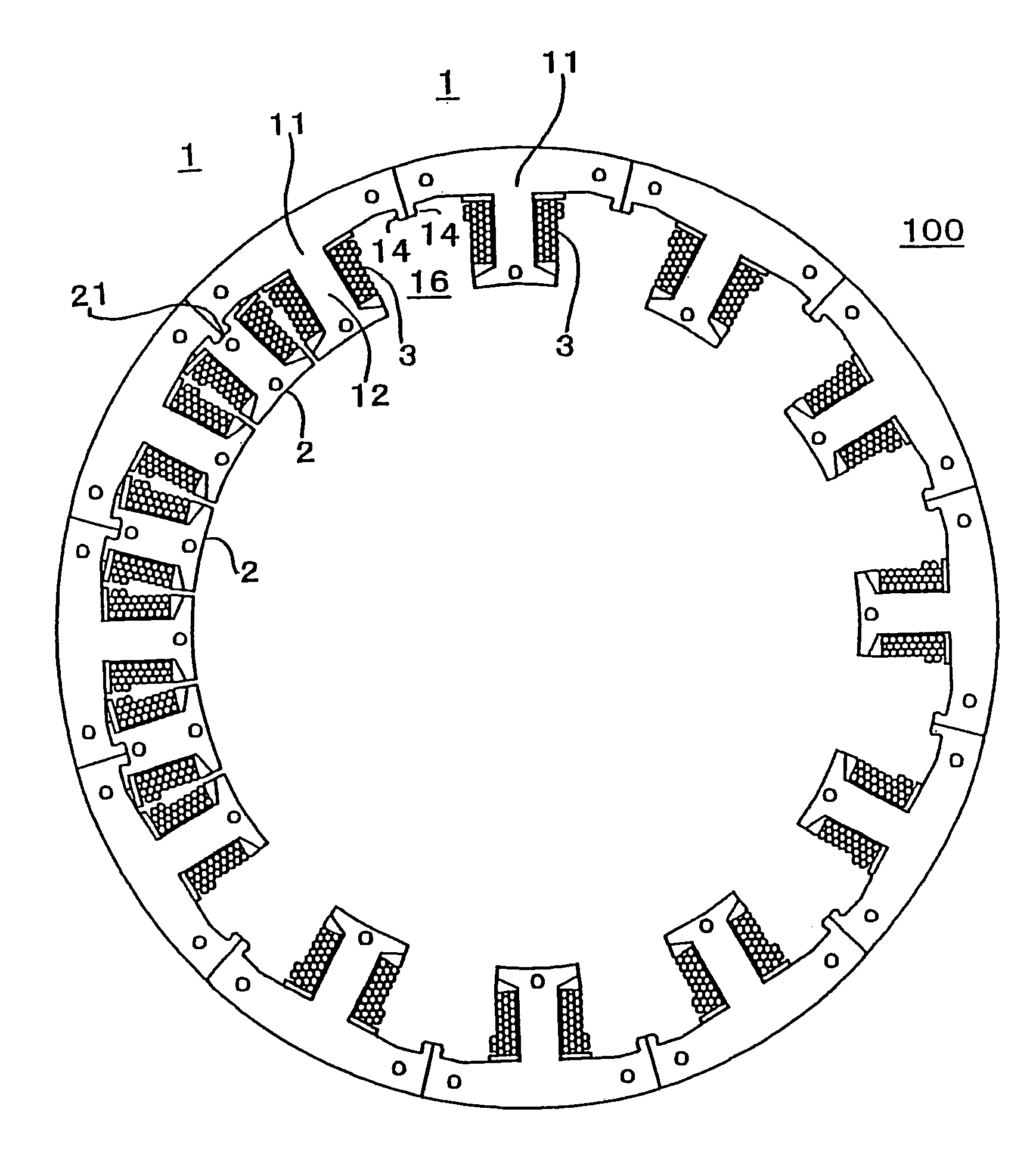
[0051]FIG. 1 is a plan view showing an armature 100 of a rotating electric machine according to a first embodiment of the invention. Here, the invention is described, by way of example, with reference to the rotating electric machine in which the armature 100 functions as a stator (stationary armature) disposed around a rotor 200 which is integrally mounted on a rotary shaft 201, the armature 100 facing the rotor 200 with a specific gap therebetween. It will be recognized from the following description that the invention is fully applicable in a similar way even when the armature is a rotor (rotating armature) integrally mounted on a rotary shaft.
[0052]The armature 100 includes a plurality of first magnetic teeth 1 arranged side by side along a circumferential direction of the rotating electric machine, a plurality of second magnetic teeth 2 joined to the first magnetic teeth 1, and coils 3 wound on both the first magnetic teeth 1 and the second magnetic teeth 2 as shown in FIG. 1. ...
second embodiment
[0061]FIGS. 6A and 6B are diagrams showing a principal portion of an armature of a rotating electric machine according to a second embodiment of the invention, FIGS. 6A and 6B corresponding to FIGS. 5A and 5B showing the first embodiment of the invention.
[0062]In the second embodiment of the invention, joint portions 14 formed along facing end surfaces 13 of yoke portions 11 of each pair of adjacent first magnetic teeth 1 do not extend all the way along the entire length L (as measured along the axial direction) of the first magnetic teeth 1 but along part of the entire length L, or length L1. While each connecting part 16 made of a pair of joint portions 14 extends to the length L1 as illustrated, a mating part 21 having a dovetail groove-shaped cross section is formed along the entire axial length L of each second magnetic tooth 2.
[0063]In this embodiment, the connecting part 16 is made shorter than the entire axial length L of the first magnetic teeth 1 as explained above. This c...
third embodiment
[0064]FIG. 7 is a plan view showing an armature 100 of a rotating electric machine according to a third embodiment of the invention, FIG. 8 is a plan view showing one of first magnetic teeth 1 of FIG. 7, and FIG. 9 is a plan view showing one of second magnetic teeth 2 of FIG. 7. The following discussion deals mainly with how the armature 100 of the third embodiment differs from the armature 100 of the first embodiment, in which elements identical or similar to those of the first embodiment are designated by the same reference numerals.
[0065]Referring to the Figures, there are formed groovelike joint portions 17 along inner edges (lower edges as illustrated in FIG. 8) of both end surfaces 13 of a yoke portion 11 of each first magnetic tooth 1. When two first magnetic teeth 1 are arranged side by side along the circumferential direction with their end surfaces 13 positioned directly against each other, the groovelike joint portions 17 of the two adjacent first magnetic teeth 1 face ea...
PUM
 Abstract
Description
Claims
Application Information