Dual band and broadband flat dipole antenna

a flat dipole antenna, broadband technology, applied in the direction of simultaneous aerial operation, antenna, antenna feed intermediate, etc., can solve the problems of dipole antenna for application products, reducing production costs, and wireless transmission system not working normally, so as to broaden the range of bandwidth of application products using the antenna of invention

Inactive Publication Date: 2006-05-09
ARCADYAN
View PDF2 Cites 24 Cited by
  • Summary
  • Abstract
  • Description
  • Claims
  • Application Information

AI Technical Summary

Benefits of technology

[0012]In view of the above, the invention is to provide a dual band and broadband flat dipole antenna, which can increase the working bandwidth and can be simultaneously applied in two different frequency bands.
[0017]As mentioned above, the dual band and broadband flat dipole antenna of the invention utilizes the first frequency-radiating parts and the second frequency-radiating parts to achieve the function of dual band and to achieve the function of broadband according to the structure and the configuration of the first radiating body and the second radiating body. Therefore, the usable range of bandwidth of the application products with the antenna of the invention is broadened, so that the application products with the antenna can be used in more countries.

Problems solved by technology

The wireless transmission system would not work normally such as radiating or receiving data if it lack of the antenna.
Choosing the suitable antenna not only can be contributive to collocate the appearance of product and to increase transmission characteristics, but also can decrease the production cost.
As mentioned above, the conventional dipole antenna only covers a part of the bandwidth, and the dipole antenna for application products, therefore, is unable to be applied in different countries because the available bandwidth is probably restricted in different countries or areas.

Method used


Image

  • Dual band and broadband flat dipole antenna
  • Dual band and broadband flat dipole antenna
  • Dual band and broadband flat dipole antenna

Examples


Embodiment Construction

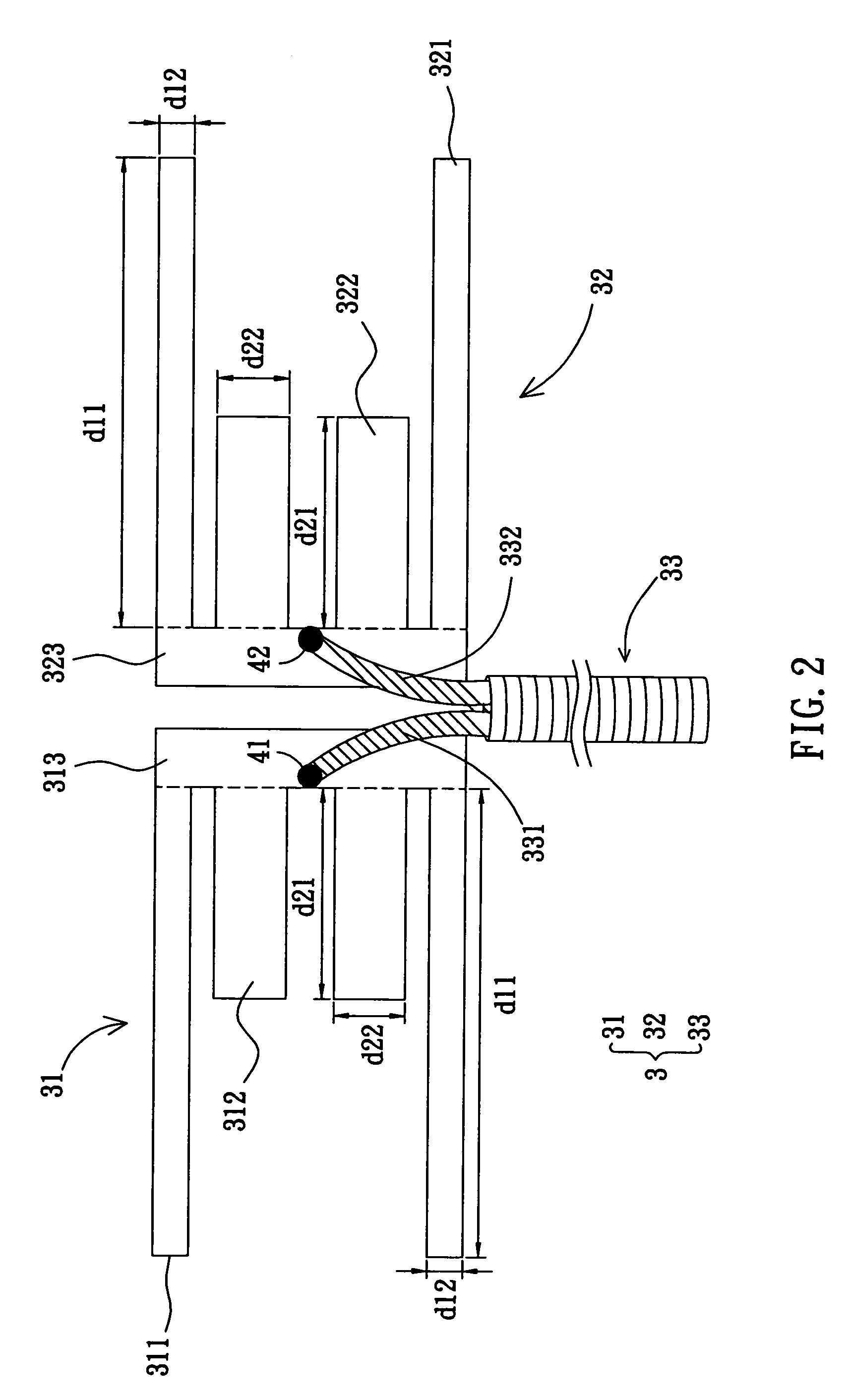
[0023]The dual band and broadband flat dipole antenna of the invention will be apparent from the following detailed description, which proceeds with reference to the accompanying drawings, wherein the same references relate to the same elements.

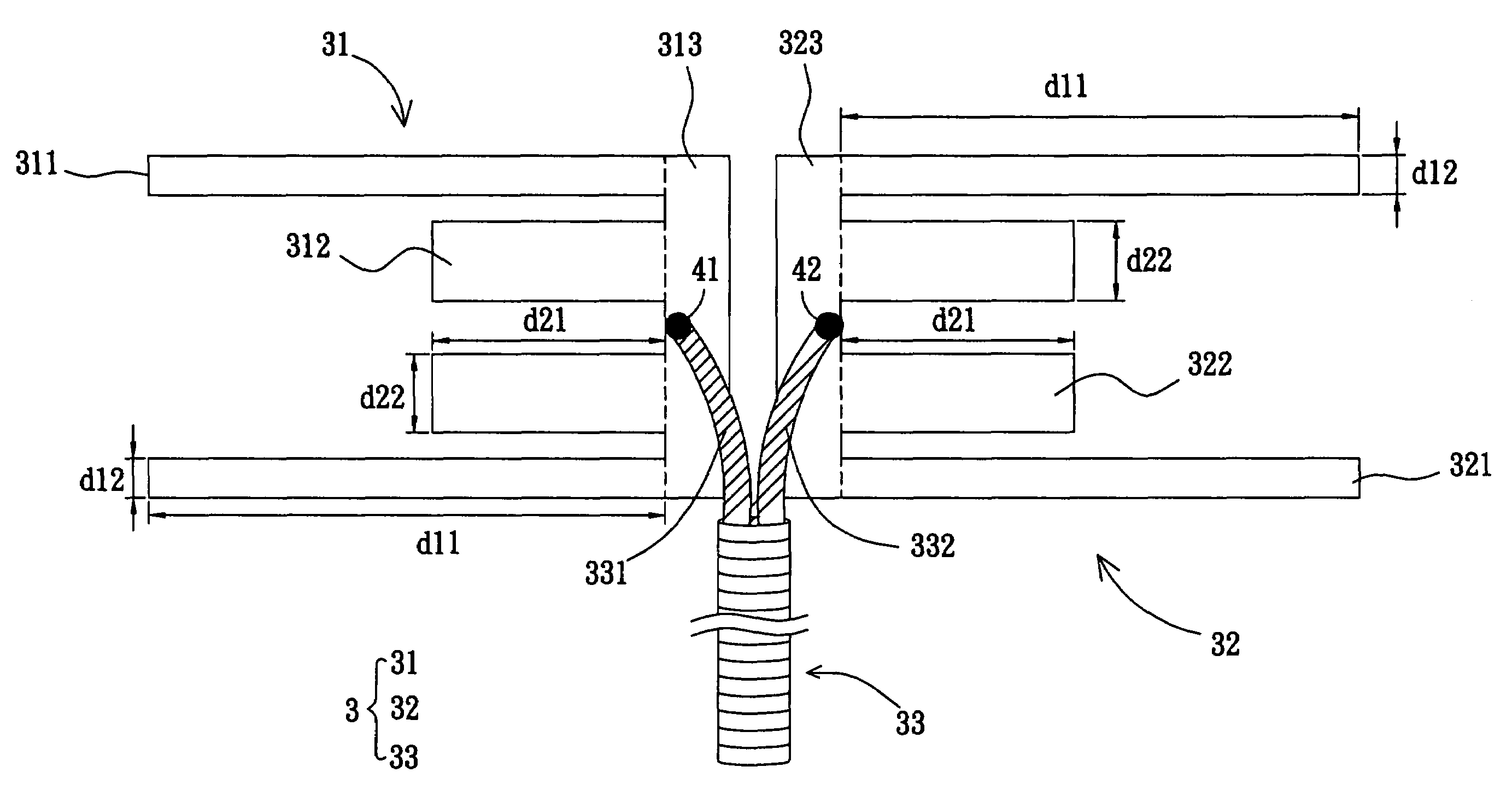
[0024]Referring to FIG. 2, a dual band and broadband flat dipole antenna 3 according to an embodiment of the invention includes a first radiating body 31, a second radiating body 32, and a conductivity element 33.

[0025]The first radiating body 31 has at least two first frequency-radiating parts 311, at least two second frequency-radiating parts 312, and a first electrically connecting part 313. In the embodiment, the first frequency-radiating parts 311 and the second frequency-radiating parts 312 are rectangular.

[0026]Each the first frequency-radiating part 311 has a first length d11 and a first width d12. Each second frequency-radiating part 312 has a second length d21 and a second width d22. The second width d22 is greater than or equal to ...


PUM


Abstract

A dual band and broadband flat dipole antenna comprises a first radiating body, a second radiating body, and a conductivity element. The first radiating body has two first frequency-radiating parts, two second frequency-radiating parts, and a first electrically connecting part. The first and second frequency-radiating parts are extended from a side of the first electrically connecting part. The second frequency-radiating parts are disposed between the first frequency-radiating parts. The second radiating body similar to the first radiating body has two first frequency-radiating parts, two second frequency-radiating parts, and a second electrically connecting part. The first and second frequency-radiating parts are extended from a side of the second electrically connecting part with the direction reversing to the extending direction of the first radiating body. The conductivity element has a conductivity body and a grounding conductor electrically connected with the first electrically connecting part and the second electrically connecting part, respectively.

Description

BACKGROUND OF THE INVENTION[0001]1. Field of Invention[0002]The invention relates to an antenna and, in particular, to a dual band and broadband flat dipole antenna, which can increase the operation bandwidth of the antenna for applications in more countries or areas.[0003]2. Related Art[0004]The prosperous development of wireless transmission industry has carried out various products and techniques for multi-band transmission, so that many new products have the wireless transmission function so as to meet the consumer's demands.[0005]The antenna, which is used for radiating or receiving the electromagnetic wave, is an important component in the wireless transmission system. The wireless transmission system would not work normally such as radiating or receiving data if it lack of the antenna. Therefore, the antenna is indispensable in the wireless transmission system.[0006]Choosing the suitable antenna not only can be contributive to collocate the appearance of product and to increa...

Claims


Application Information

Patent Timeline
Patent Type & Authority Patents(United States)
IPC IPC(8): H01Q9/16
CPCH01Q5/371H01Q9/28
Inventor CHENG, SHIH-CHIEH
Owner ARCADYAN
Why Eureka
Try Eureka