Ground terminal and method for mounting a printed board mounted with a ground terminal to a chassis

a ground terminal and printed board technology, applied in the direction of connection contact member materials, coupling device connections, radio transmission connectors, etc., can solve the problems of large connection resistance, difficult to be downsized, complicated shape, etc., to improve the electrical connection between the ground terminal and the chassis, simplify the construction of the ground terminal, and reduce the effect of downsizing

Inactive Publication Date: 2006-05-16
KYOSHIN KOGYO CO LTD
View PDF11 Cites 23 Cited by
  • Summary
  • Abstract
  • Description
  • Claims
  • Application Information

AI Technical Summary

Benefits of technology

[0015]The ground terminal body may be used to establish electrical connection with a printed board to which the ground terminal is mounted. For instance, the ground terminal body is soldered to a solder portion formed as a connection portion in the printed board. In this case, it is unnecessary to additionally provide the ground terminal with a connection portion such as a solder portion used to establish electrical connection with the printed board, making it possible to simplify the construction of the ground terminal and to downsize the ground terminal.
[0016]According to another aspect of this invention, there is provided a method for mounting a printed board mounted with a ground terminal to a chassis, which comprises the steps of: (a) preparing a ground terminal comprising a ground terminal body formed into an annular shape as viewed in plan, and at least one connection portion formed integrally with the ground terminal body, the connection portion being bendable and extending from an inner circumference of the ground terminal body toward a center of the ground te...

Problems solved by technology

However, the above-mentioned prior art ground terminal which is complicated in shape and difficult to be downsized is not suitable for use in a small-sized equi...

Method used


Image

  • Ground terminal and method for mounting a printed board mounted with a ground terminal to a chassis
  • Ground terminal and method for mounting a printed board mounted with a ground terminal to a chassis
  • Ground terminal and method for mounting a printed board mounted with a ground terminal to a chassis

Examples


first embodiment

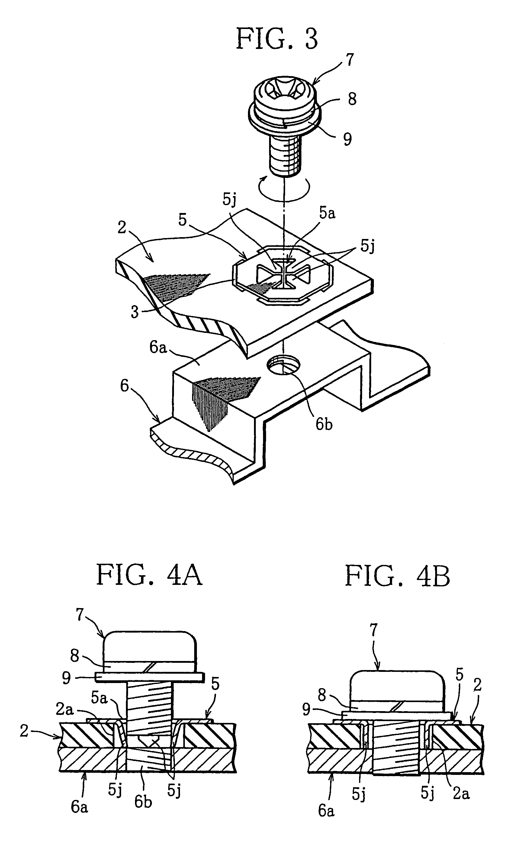
[0031]In the following, a ground terminal and a method for mounting a printed board mounted with the ground terminal to a chassis will be explained.

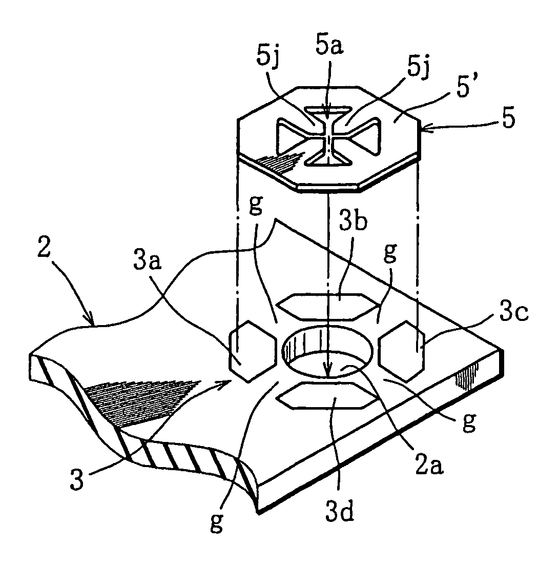
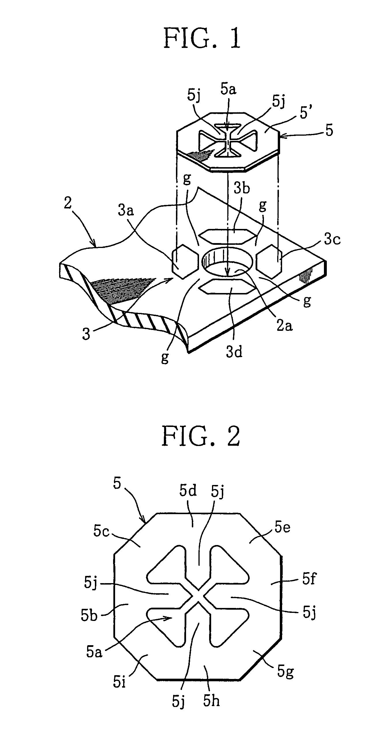
[0032]Referring to FIG. 2, the ground terminal 5 of this embodiment, which is fabricated for example by stamping a metal sheet, comprises a ground terminal body 5′ having terminal body portions 5b–5i and formed into an annular shape as viewed in plan, and a plurality of, for example, four connection portions (hereinafter referred to as first through fourth connection portions) 5j that are tongue pieces formed integrally with the ground terminal body 5′. A cross recess 5a is defined between the ground terminal body 5′ and the first through fourth connection portions 5j. The ground terminal body may be formed into a circular annular shape or a polygonal annular shape as viewed in plan. The ground terminal body 5′ of this embodiment is formed into an octagonal annular shape having an octagonal outer circumference and an octagonal inner cir...

second embodiment

[0045]The ground terminal 11 of the second embodiment shown in FIG. 5 comprises first through fourth connection portions 11j extending from an annular ground terminal body, having an octagonal outer circumference and an octagonal inner circumference, toward the center of the ground terminal 11. Each of the connection portions 11j has a first and a second widthwise half. The first half of each connection portion 11j is formed at it tip end with a notch 11k. The tip end 11m of the second half of each connection portion 11j enters the notch 11 k of the adjacent connection portion 11j . When the connection portions 11j are bent along the inner circumference of the annular ground terminal body upon insertion of a mounting screw to connect a printed board mounted with the ground terminal 11 to a chassis, the tip ends 11 m of the connection portions 11j are brought in direct contact with the chassis.

[0046]As understood from the foregoing explanation, the ground terminal 11 is characterized...

third embodiment

[0047]The ground terminal 12 of the third embodiment shown in FIG. 6 includes first through fourth connection portions 11j extending from an annular ground terminal body, having an octagonal outer circumference and an octagonal inner circumference, toward the center of the ground terminal 12. The second and fourth connection portions 12j′ have their length which is shorter than the length of the first and third connection portions 12j, so that tip ends of the first and third connection portions 12j may enter between tip ends of the second and fourth connection portions 12j′. When the first though fourth connection portions 11j are bent along the inner circumference of the annular ground terminal body, the tip ends of the first and third connection portions are brought in direct contact with the chassis.

[0048]The ground terminal 12 is characterized in that the two connection portions 12j are made as long as possible while preventing interference between the connection portions 12j , ...


PUM


Abstract

A ground terminal capable of being downsized and having good electrical connectability with a chassis. The ground terminal includes a ground terminal body formed into an annular shape as viewed in plan, and at least one connection portion formed integrally with the ground terminal body, the connection portion being bendable and extending from an inner circumference of the ground terminal body toward the center of the ground terminal. When a mounting screw used to mount a printed board mounted with the ground terminal to a chassis is inserted into the annular ground terminal body and a mounting hole of the printed board, the connection portion of the ground terminal is bent in the mounting hole to be brought in contact with the chassis.

Description

CROSS-REFERENCE TO A RELATED APPLICATION[0001]This nonprovisional application claims priority under 35 U.S.C. §119(a) on Patent Application No. 2003-114555 filed in Japan on Apr. 18, 2003, the entire contents of which are hereby incorporated by reference.BACKGROUND OF THE INVENTION[0002]1. Field of the Invention[0003]The present invention relates to a ground terminal and a method for mounting a printed board mounted with a ground terminal to a chassis.[0004]2. Description of the Related Art[0005]In electronic equipment, especially in a vehicle-mounted audio equipment, it is essentially required to take a measure to reduce noise. To this end, a ground terminal is mounted on a printed board and electrically connected to a chassis, so that the printed board is grounded to the chassis. Such a ground terminal is disclosed for example in Japanese patent publication no. 2863981. As shown in FIG. 11, this ground terminal 1 comprises a first longitudinal half and a second longitudinal half w...

Claims


Application Information

Patent Timeline
IPC IPC(8): H01R13/648H01R4/64H01R12/57H01R13/658H01R43/20H05K9/00
CPCH01R4/64H01R12/57H01R13/65802H05K9/0039H01R43/205Y10S439/927H01R2201/24H01R2201/26H01R4/34H01R13/652
Inventor HATAKEYAMA, TOSHIHIRO
Owner KYOSHIN KOGYO CO LTD
Why Eureka
Try Eureka