RFID device detection system and method

a technology of rfid devices and detection systems, applied in the field of methods of detecting rfid tags and labels, can solve the problems of difficulty in special discrimination in reading and detection of devices, inability to use small or inexpensive items, and inability to detect devices at the same tim

Active Publication Date: 2006-06-13
AVERY DENNISON CORP
View PDF61 Cites 66 Cited by
  • Summary
  • Abstract
  • Description
  • Claims
  • Application Information

AI Technical Summary

Benefits of technology

[0010]According to an aspect of the invention, an RFID device detection system detects RFID devices by use...

Problems solved by technology

Thus detection of devices is accomplished over a significantly-sized region, and special discrimination in reading and detection of devices may be difficult.
Moreover, while...

Method used


Image

  • RFID device detection system and method
  • RFID device detection system and method
  • RFID device detection system and method

Examples


Embodiment Construction

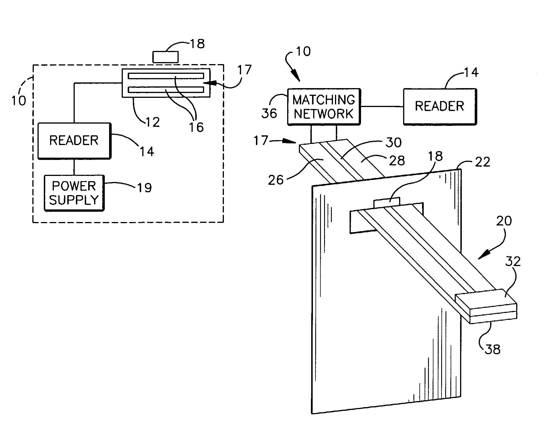
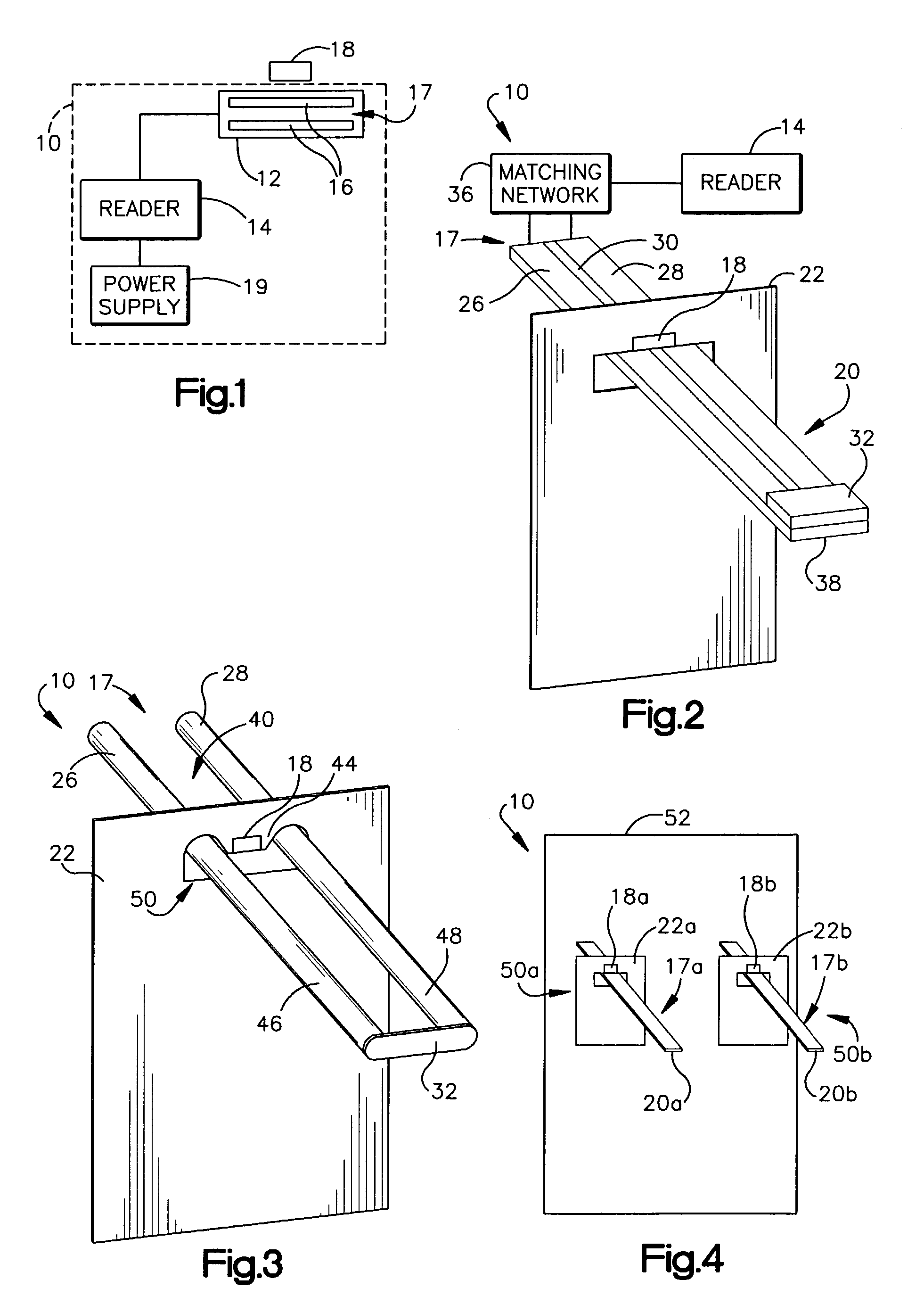
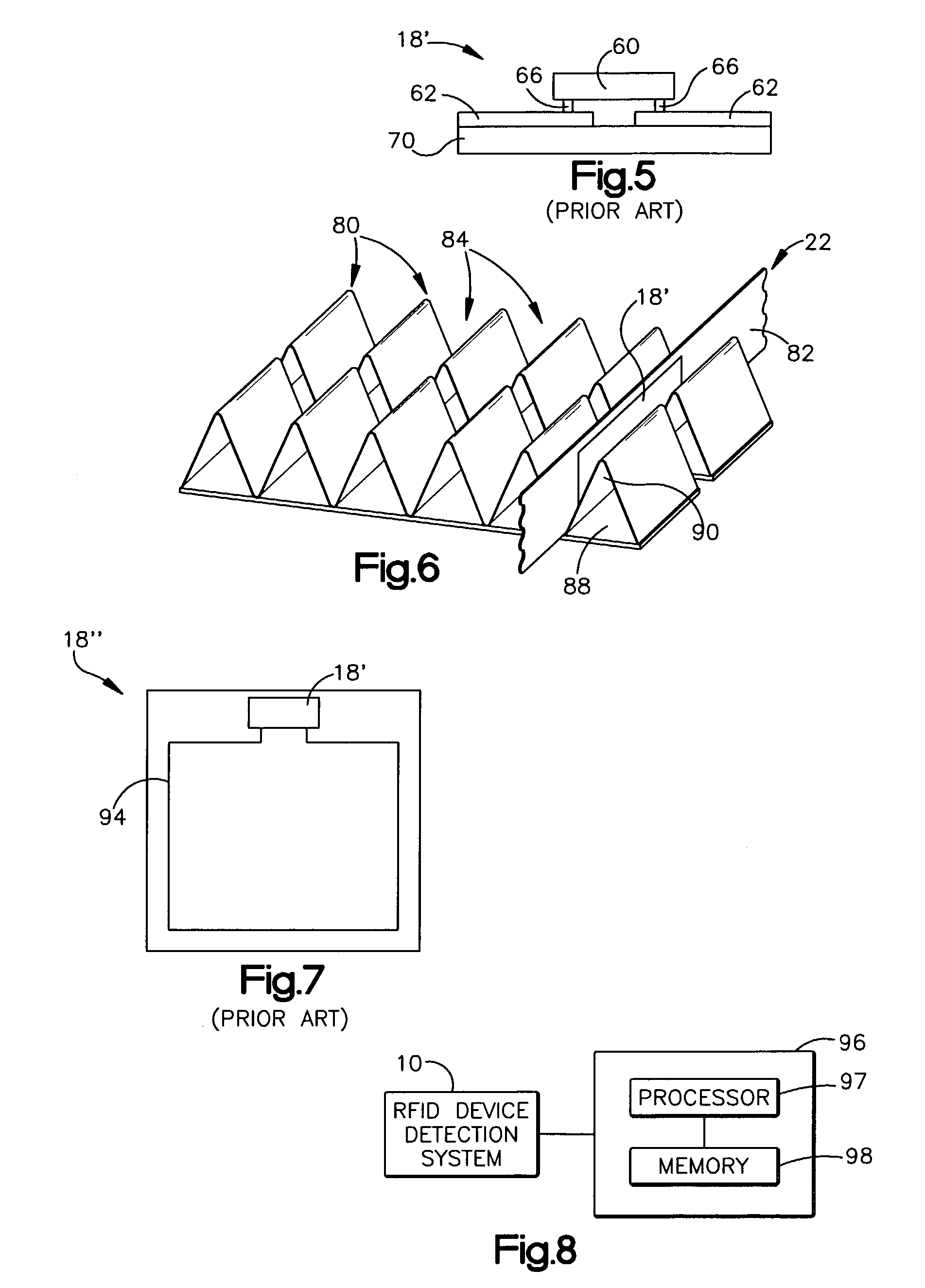
[0041]An RFID device detection system includes a proximity locator, which generates an electric field for reading an antennaless RFID device, or for reading other, antennaed RFID devices. An antennaless RFID device includes non-antenna conductive leads coupled to a chip. The proximity locator includes one or more conductors forming a transmission line structure arranged to set up a strong RF electric field in proximity to the locator. The strong RF electric field may be a short-range field that provides significant RF energy only over a relatively short distance, when compared with traditional RF fields that are set up over a relatively large distance. The short-range RF field allows coupling to antennaed and antennaless RFID devices that are near to the proximity locator. The RFID device detection system may be employed in a variety of tasks, including inventory control and theft detection.

[0042]As used herein, the term “antennaless” refers broadly to devices lacking an antenna tha...


PUM


Abstract

An RFID device detection system includes a proximity locator, which generates an electric field for reading an antennaless RFID device, or for reading other, antennaed RFID devices. An antennaless RFID device includes non-antenna conductive leads coupled to a chip. The proximity locator includes one or more conductors forming a transmission line structure arranged to set up a strong RF electric field in proximity to the locator. The strong RF electric field may be a short-range field that provides significant RF energy only over a relatively short distance, when compared with traditional RF fields that are set up over a relatively large distance. The short-range RF field allows coupling to antennaed and antennaless RFID devices that are near to the proximity locator. The RFID device detection system may be employed in a variety of tasks, including inventory control and theft detection.

Description

BACKGROUND OF THE INVENTION[0001]1. Field of the Invention[0002]This invention relates to the field of radio frequency identification (RFID) tag and label detection systems, and to methods of detecting RFID tags and labels.[0003]2. Description of the Related Art[0004]Radio frequency identification (RFID) tags and labels (collectively referred to herein as “devices”) are widely used to associate an object with an identification code. RFID devices generally have a combination of antennas and analog and / or digital electronics, which may include for example communications electronics, data memory, and control logic. For example, RFID tags are used in conjunction with security-locks in cars, for access control to buildings, and for tracking inventory and parcels. Some examples of RFID tags and labels appear in U.S. Pat. Nos. 6,107,920, 6,206,292, and 6,262,292, all of which are hereby incorporated by reference in their entireties.[0005]As noted above, RFID devices are generally categoriz...

Claims


Application Information

Patent Timeline
IPC IPC(8): G06Q30/00G06K7/00G06K7/10
CPCG06K7/10346G06K7/0008
Inventor FORSTER, IAN J.
Owner AVERY DENNISON CORP
Why Eureka
Try Eureka