Dispensing container

a technology for discharging containers and containers, applied in the direction of liquid transferring devices, pliable tubular containers, instruments, etc., can solve the problems of clogging or bacterial growth of filters, contamination of containers, and contaminating liquid content, so as to achieve high sanitary and safe discharge

Active Publication Date: 2006-09-12
YOSHINO KOGYOSHO CO LTD
View PDF19 Cites 16 Cited by
  • Summary
  • Abstract
  • Description
  • Claims
  • Application Information

AI Technical Summary

Benefits of technology

[0011]The content in the inner container is discharged by the squeeze of the body of the outer container. When the squeeze is stopped and the pressure is released, the discharge of the content comes to a halt. The body of the outer container begins restoring its original shape due to a resilient force. The first check valve, which has been assembled with, and tightly fitted to, the inner neck, shows the action and effect to prevent the back flow of the content and the entry of outside air into the inner container.
[0027]Because airborne bacteria and foreign matters, such as dust, can be prevented from creeping in the inside of the container, a highly sanitary and safe discharge container can be provided for use as an eyedropper.

Problems solved by technology

At that time, the container faces a problem as outside air creeps in the container along with airborne foreign matters and bacteria, which may contaminate the liquid content.
However, the method of adding a filter inside the content discharge path has problems of filter clogging or bacterial growth in the filter.
The method of flattening the end of the container according to utility model laid open No. 1988-183047 is mainly an application of toothpaste tubes, and had a problem of inconvenience in use and a problem of outer appearance.
Especially, the discharge cap not only connects and fixes the outer and inner containers to each other, but also is provided with the function of an air intake valve, which is able to take in outside air and would not allow air to escape outside.
In the case of small-size discharge containers such as eyedroppers, it is difficult, and not feasible in reality, for the container to have such a function while maintaining high productivity.

Method used


Image

  • Dispensing container
  • Dispensing container
  • Dispensing container

Examples


Embodiment Construction

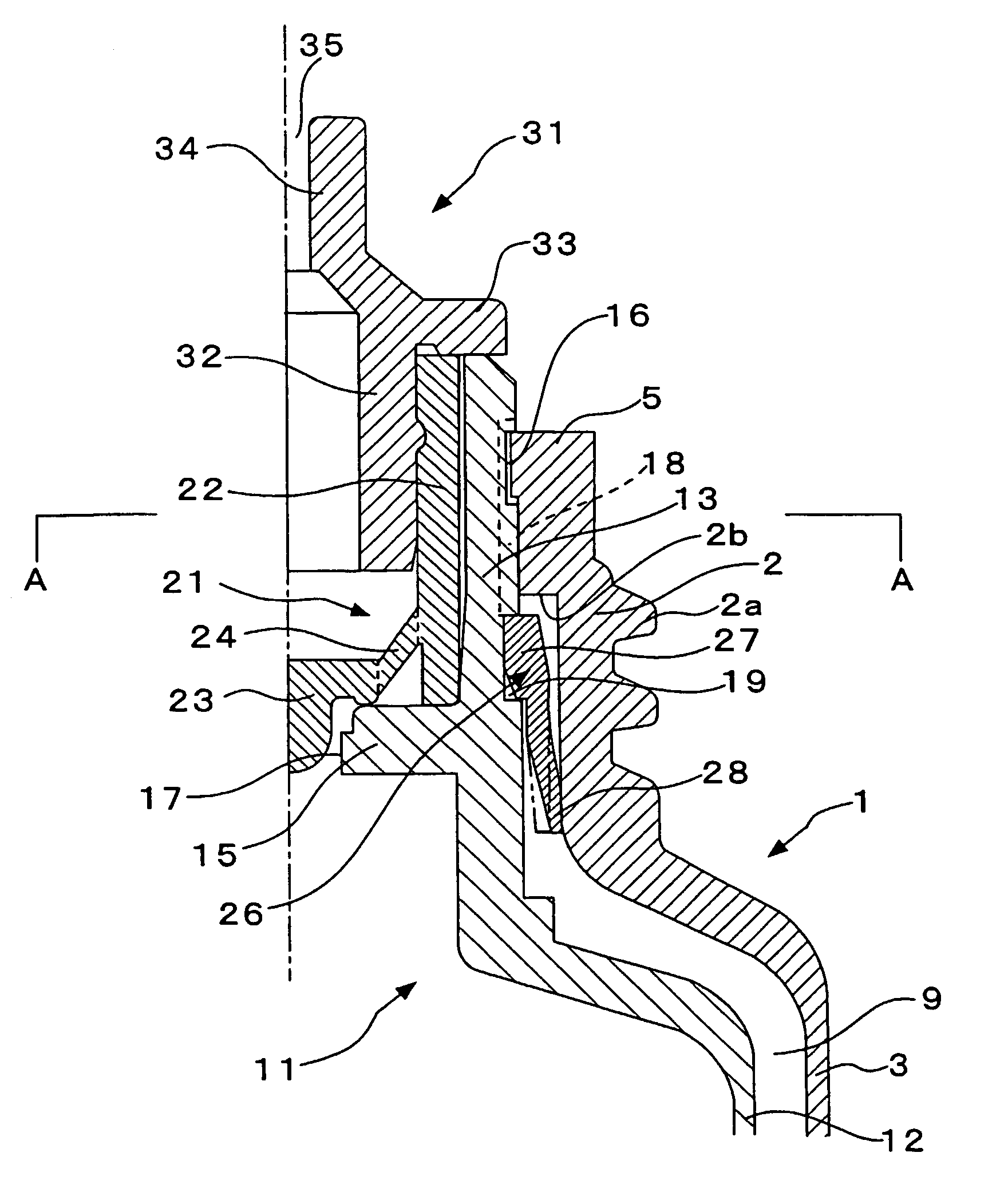
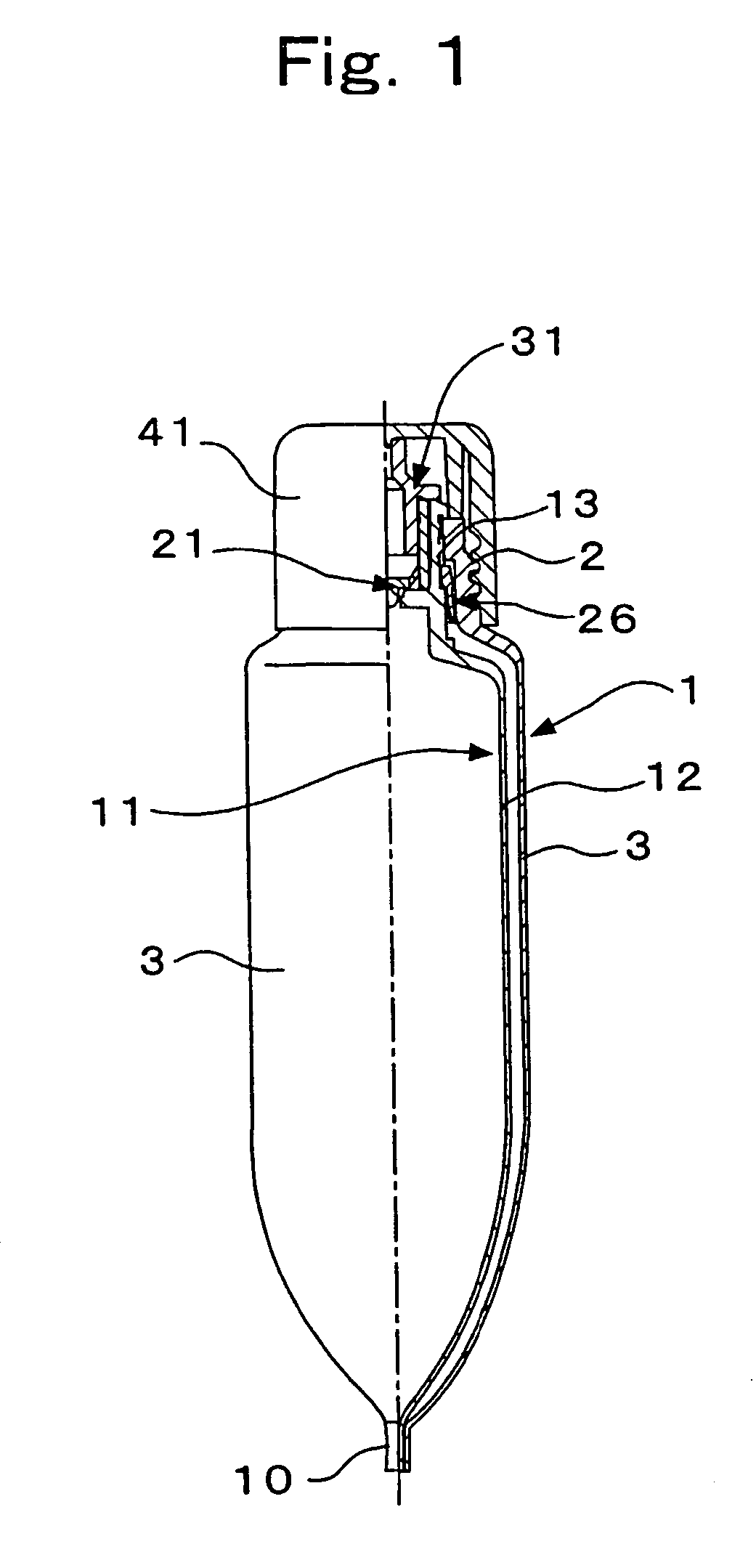
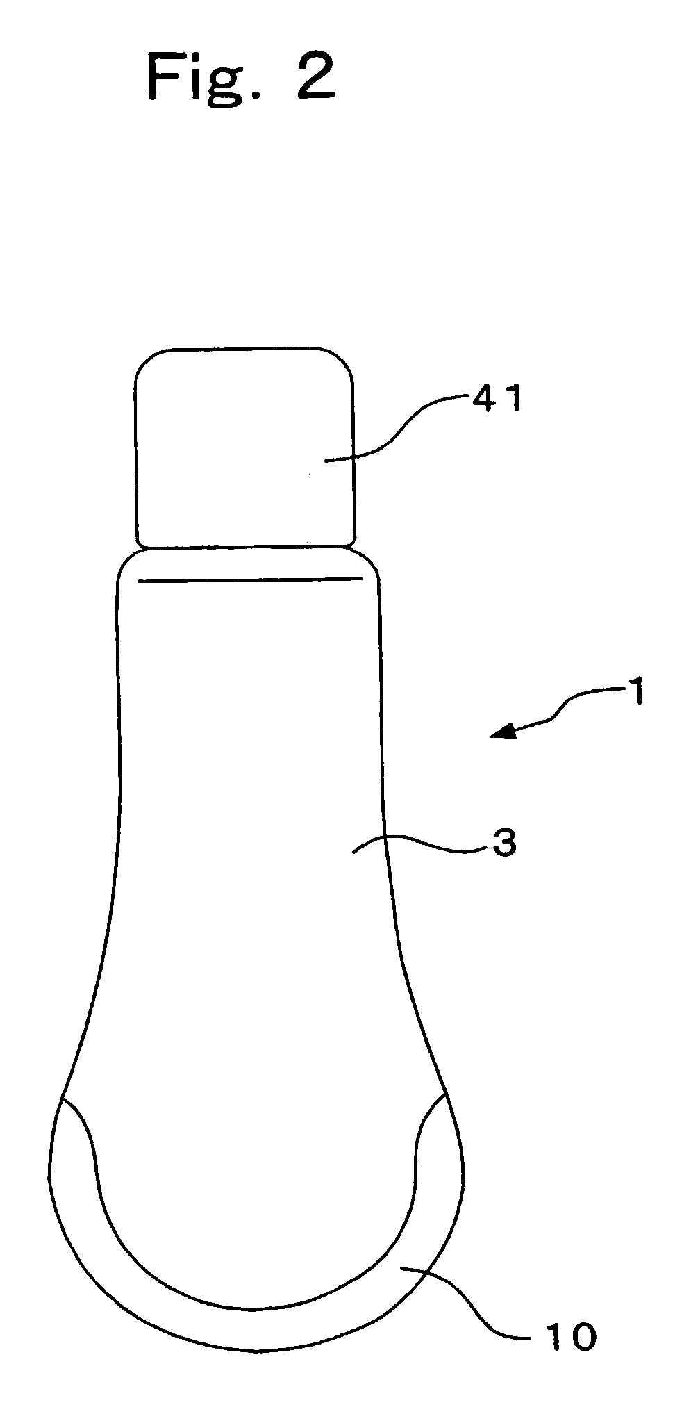
[0033]This invention is further described with respect to preferred embodiments of this invention, now referring to the drawings. FIGS. 1–5 show a discharge container in an embodiment of this invention, which comprises an outer container 1, an inner container 11, the first check valve mechanism 21, the second check valve mechanism 26, and a discharge section 31. Among them, the inner container 11 and the discharge section 31 are made of a hard synthetic resin. The first check valve mechanism 21 and the second check valve mechanism 26 are made of a soft synthetic resin or a rubber material. (Hereinafter this invention is described mainly referring to FIG. 3, which is a longitudinal section, with the most important portion being enlarged.)

[0034]The outer container 1 comprises an outer body 3 having the flexibility to make it squeezable and restorable to its original shape, and also comprises a cylindrical outer neck 2, which is provided on the upper part of the outer body 3 by way of ...


PUM


Abstract

The first and second check valve mechanisms, which are applicable to a small-size double-layered container, are created while maintaining high productivity. The discharge container provided with these check valve mechanisms comprises an outer container, which has the flexibility to make this outer container squeezable and recoverable to its original shape and which is provided with a cylindrical outer neck on top thereof. This discharge container also comprises an inner container, which is deformable with the decrease in the content and is disposed inside the outer container under the condition that cylindrical inner neck has been directly engaged with, and tightly fitted to, the outer neck. The first check valve mechanism is engaged with, and tightly fitted to, the inside of the inner neck and is used to open or close the opening of the inner neck while preventing outside air from creeping in the inner container. The second check valve mechanism is engaged with, and tightly fitted to, either one of the outer neck or the inner neck, with the lower end of this mechanism being in tight contact circumferentially with the other one of the outer neck or the inner neck, and is used to open or close airflow paths, which extends from the upper air intakes near the outer neck in a manner that allows outside air to enter the void between the outer and inner containers but does not allow air in the void to escape outside. There is thus provided a highly sanitary discharge container having high productivity and affording no entry of outside air into the inner container.

Description

TECHNICAL FIELD[0001]This invention relates to a discharge container, such as an eyedropper, from which the content can be discharged while preventing outside air from creeping into the discharge container, especially into the inside of the inner container.BACKGROUND OF THE INVENTION[0002]Various small-size containers are in use to contain liquid medicines, such as eye drops, and to discharge medicines therefrom, drop by drop, by squeezing the body of the container with fingers. The body resiliently restores its original shape as soon as the pressure is released after the discharge. At that time, the container faces a problem as outside air creeps in the container along with airborne foreign matters and bacteria, which may contaminate the liquid content.[0003]As the means of solving this problem, Japanese patent applications P1992-297264 and P1994-14972 describe a method of adding a filter inside the content discharge path. Utility model laid open No. 1988-183047 describes a method ...

Claims


Application Information

Patent Timeline
Patent Type & Authority Patents(United States)
IPC IPC(8): B65D37/00B65D25/04B65D35/22B65D35/56B67D5/42B65D25/00B65D47/20B65D47/32B65D83/00B67D7/60
CPCB65D47/2031B65D83/0055B65D47/32B65D47/2075B65D35/22
Inventor SUZUKI, KAZUO
Owner YOSHINO KOGYOSHO CO LTD
Why Eureka
Try Eureka