
Apparatus for optically coupling a light source with an optical waveguide
a technology of optical waveguides and light sources, applied in the field of optical beam steering, can solve the problems of limiting the available beam steering angles to discrete angular increments, prone to crosstalk, and the digital nature of these devices
Patent Information
- Authority / Receiving Office
- US · United States
- Patent Type
- Patents(United States)
- Current Assignee / Owner
- Publication Date
- 2006-12-19
- Estimated Expiration
- Not applicable · inactive patent
Smart Images
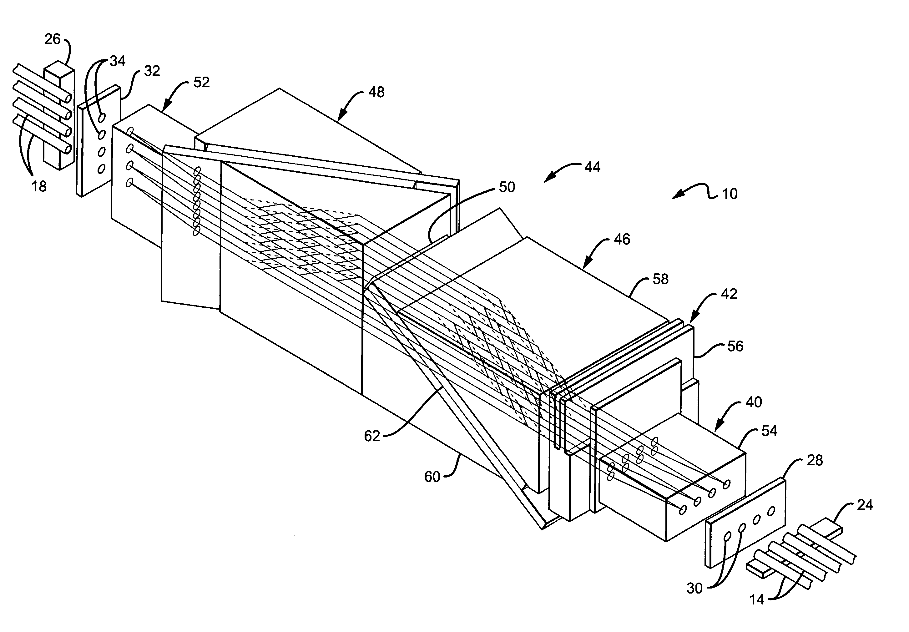
Figure 1 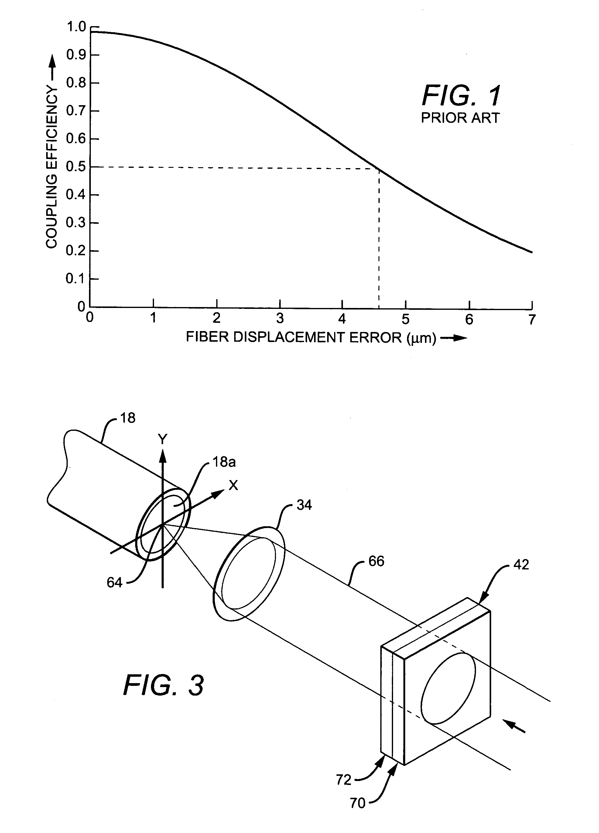
Figure 2 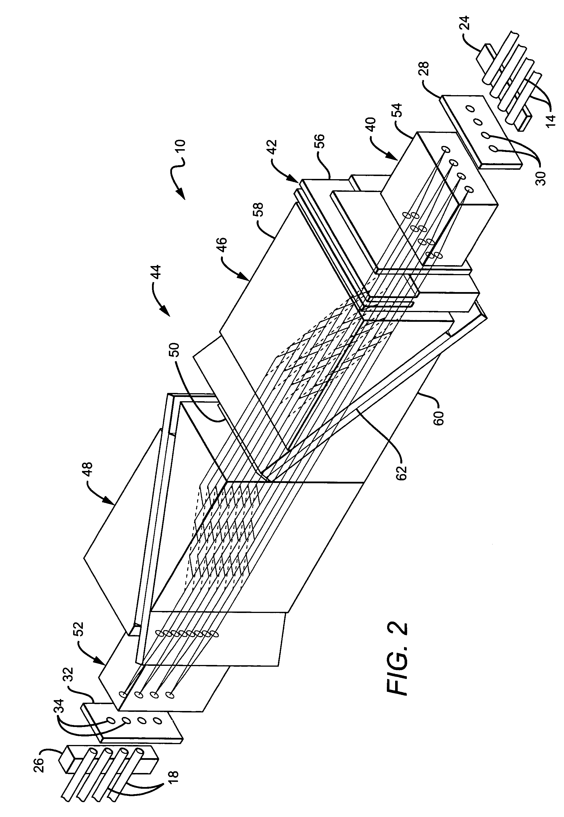
Figure 3
Abstract
Description
CROSS REFERENCE TO RELATED APPLICATION
[0001] This is a divisional of U.S. patent application Ser. No. 10 / 267,282, filed on Oct. 8, 2002 now U.S. Pat. No. 6,832,028.BACKGROUND OF THE INVENTION
[0002] 1. Field of the Invention
[0003] The present invention relates generally to optical beam steering and particularly to an optical system utilizing the electro-optical properties of liquid crystals to steer a light beam relative to a light-receiving end of an optical waveguide such as an optical fiber.
[0004] 2. Description of the Related Art
[0005] N×N optical cross connect switches used, for example, in telecommunications systems, optically couple any one of N input optical fibers to any one of N output optical fibers. Such switches comprise examples of systems that make use of various techniques for deflecting or steering a light beam emitted from a light source, in this case the light-emitting end of a selected one of the N input fibers, to the light-receiving end of an optical waveguide, here ...
Examples
Embodiment Construction
[0037]It will be evident to those skilled in the art that the present invention has broad utility, being applicable, by way of example and not limitation, to cross bar switches; filter arrays; attenuator arrays; antenna arrays; laser systems utilizing, for example, laser diode sources for communications or other purposes; and so forth, employing optical channels or waveguides which may take the form of optical fibers.
[0038]With reference to FIG. 2, there is shown a specific example of how the present invention may be applied. The example of FIG. 2 comprises a form of an N×N liquid crystal optical cross connect switch 10 for use, for example, in a data communications or telecommunications system.
[0039]In the specific, exemplary N×N optical switch shown in FIG. 2, N=4 so that the switch 10 can couple any selected one of four longitudinally oriented input fibers 14 with any selected one of four longitudinally oriented output fibers 18.
[0040]A support 24 secures the light-emitting ends ...