Insulation displacement connector

a technology of displacement connector and insulation, applied in the direction of contact members penetrating/cutting insulation/cable strands, coupling device connections, electrical apparatus, etc., can solve the problems of reducing durability, stress concentration, and reducing durability, so as to prevent excessive strain and prevent a change in the contact resistance value or a degradation of the conductor

Inactive Publication Date: 2007-01-02
MOLEX INC
View PDF11 Cites 8 Cited by
  • Summary
  • Abstract
  • Description
  • Claims
  • Application Information

AI Technical Summary

Benefits of technology

[0008]It is a general object of the present invention to achieve IDT contact of the wire while retaining it properly in its normal and right position and also prevent excessive strain from being exerted on the conductor of the wire, thereby preventing a change in the contact resistance value or a degradation of the conductor.
[0010]According to the above arrangement, the insertion of the wire into the guide hole provided in the cover housing serves to ensure fixing of the wire in its normal position with respect to the wire connection direction. Further, while this state is being maintained by the wire holder, the cover housing provided with the wire holder moves into the base housing so that the wire is fixed to an appropriate position of the IDT terminal, thereby performing wire connection by the IDT contact in an extremely accurate manner. That is, because the wire can be brought into contact with the IDT terminal while remaining fixed in its normal position and in a state in which it is being pressed on the IDT terminal, a variation in the contact resistance is mitigated.
[0011]Further, since the wire is not forcibly pushed into the slot of the IDT terminal from its non-normal position, there is no excessive strain on the inner conductor of the electric wire. Therefore, since excessive concentration of stress does not occur in the conductor, it is possible to prevent degradation of the conductor as well as an increase in the contact resistance value resulting from contact failure of a part of the conductor.
[0012]Further, as a method for connecting a wire applied with an insulation to an IDT connector, the normal position of the wire in relation to the IDT terminal can be ensured by using a method including: a first step of inserting the wire into a guide hole inside a cover housing and temporarily locking the wire by a wire normal-position fixing means; a second step of retaining the wire by a wire holder provided to the cover housing; and a third step of pressing the wire holder and the cover housing toward a base housing by applying pressure thereon from the outside to bring the wire into IDT contact with an IDT terminal, thereby bringing a inner conductor of the wire and the IDT terminal into conduction with each other.
[0014]It is desirable that, when being mounted on the cover housing, the above-mentioned wire holder is capable of being displaced to a position where it does not interfere with the wire when inserting the electric wire into the guide hole of the cover housing. With such an arrangement, the wire does not abut against the wire-retaining portion so that the wire-retaining portion does not drop off by being pressed on by the wire before the wire connection. Moreover, since the advance movement of the wire is not obstructed, it is possible to smoothly insert the wire into the wire insertion hole and maintain the wire in its normal position with respect to the connection direction thereof.
[0017]It is also possible to provide a protective guide plate for protecting a wire in a location where the electric wire-retaining portion that has been descended crosses the above-mentioned guide hole and to guide the electric wire with the protective guide plate during the insertion of the wires.

Problems solved by technology

Incidentally, by merely press-fitting the wire into the slot of the IDT terminal, there is a fear that the wire in the IDT terminal drops off, due to vibrations generated during the use of an apparatus to which the IDT connector is applied, or due to an external force such as a tension generated on the wire.
As a result, excessive strain may be exerted on the entire or part of the wire conductor, resulting in a stress concentration.
Consequently, there is a fear that one of the following problems occur: a decrease in the sectional area of the conductor occurs which causes an increase in the resistance of the terminal-wire connection; the biased state causes a gap to be produced so that a part of the conductor does not come into contact with the IDT terminal; and due to the breaking of the wire, oxidation occurs due to moisture present in the air, thus reducing durability and causing a variation in the resistance value.

Method used


Image

  • Insulation displacement connector
  • Insulation displacement connector
  • Insulation displacement connector

Examples


Embodiment Construction

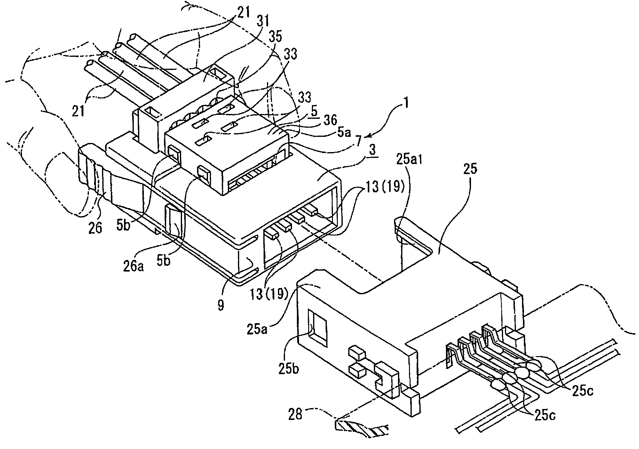
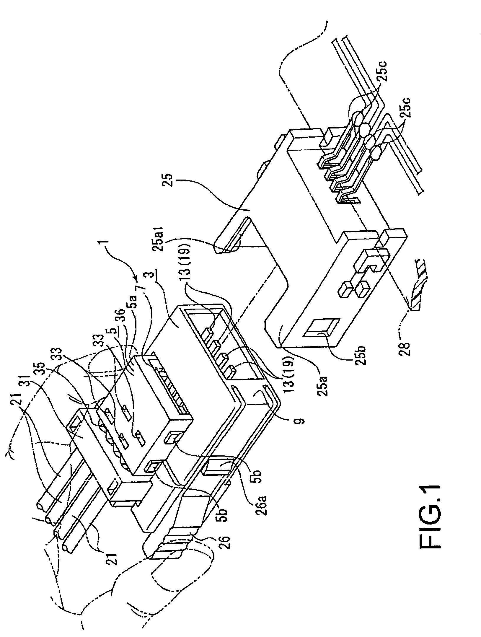
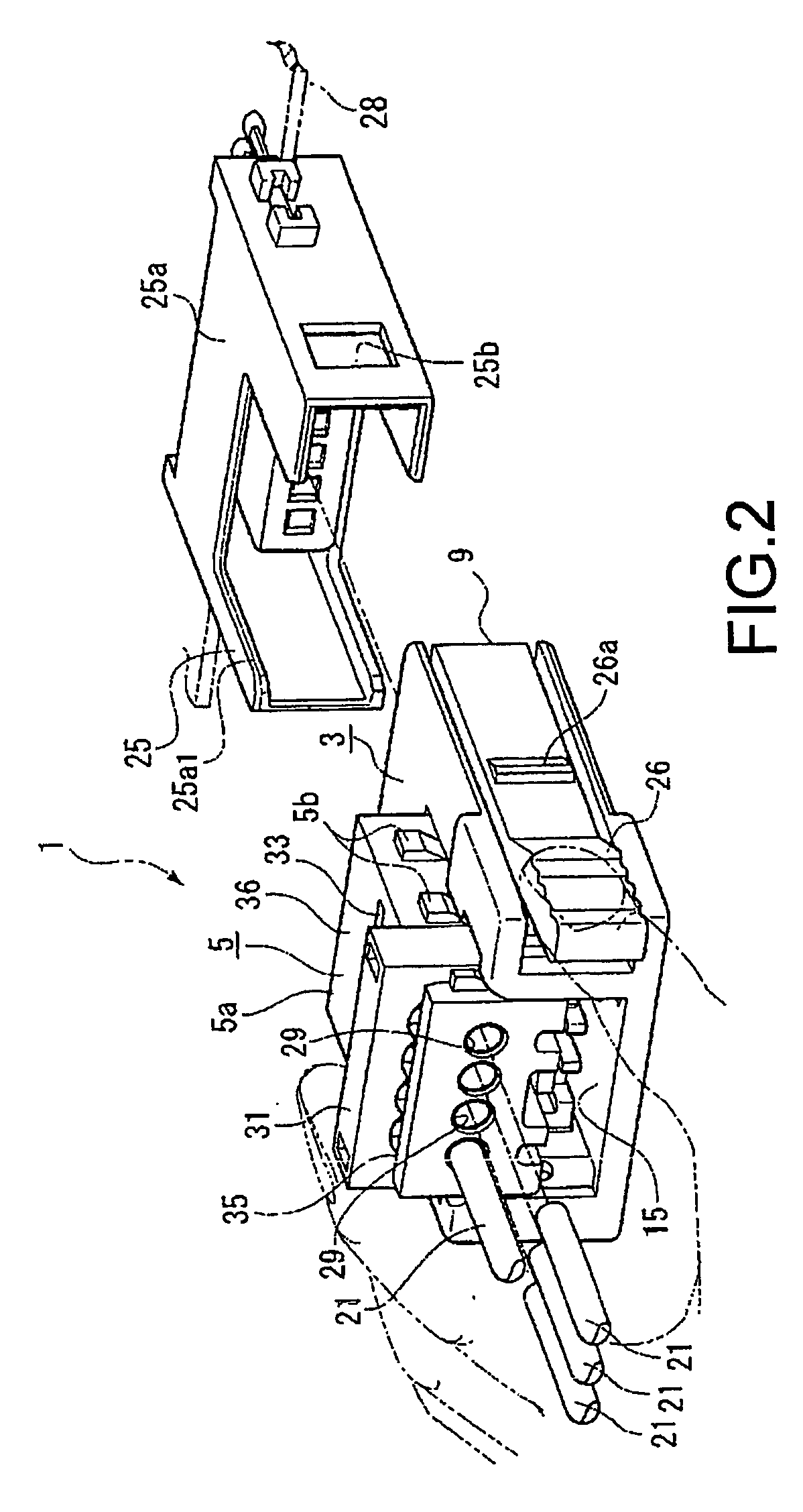
[0044]A description will be given of an IDT connector 1 according to a first embodiment of the invention with reference to FIGS. 1–20. The IDT connector 1 is a so-called plug connector, which is composed of a base housing 3 and a cover housing 5 to be overlaid on the base housing 3.

[0045]The base housing 3 includes: a terminal chamber 7 surrounded by the cover housing 5 and in which a plurality of terminals 13 are fixed; a mating section 9 which is inserted into a receptacle connector 25 serving as a mating connector of the IDT connector 1; and a partition wall 11 located between the terminal chamber 7 and the mating section 9 (see FIG. 10).

[0046]The terminal chamber 7 defines a bed in which plural (four in this embodiment) terminals 13 serving as IDT terminals are fixed onto a bottom surface 15 thereof (see FIGS. 10, 14 etc.).

[0047]Each terminal 13 is stamped and formed from sheet metal of phosphorus bronze. As can be seen in FIG. 10, in its side view, the terminal 13 has a shape s...


PUM


Abstract

An IDT connector (1) is provided which includes: a base housing (3) having a terminal (19) to which a wire (21) is press-fit; a cover housing (5) mounted to the base housing (3) and having a wire insertion hole (29) into which the wire (21) is inserted; a wire holder (31) which is provided to the cover housing, for pressing the wire that is to be press-fitted to the terminal; and an IDT contact slot extending orthogonal to the wire insertion hole and formed adjacent to the wire holder with respect to the longitudinal direction of the wire insertion hole.

Description

BACKGROUND OF THE INVENTION[0001]The present invention relates generally to a connector used for connecting insulated electric wires to various electrical parts or a printed circuit board, or for interconnecting a plurality set of electrical wires.[0002]A connector with Insulation Displacement Technology Connection (“IDT”) has been widely used for making a permanent electrical interface between a wire and a contact of a connector. In this method, insulated wires are forced into a slot smaller in width than the diameter of the inner conductor of the wire. The sharp thin edges of the slot displace the outer insulation and electrical continuity is secured. The slot of the IDT terminals typically have V or U-shaped slots obtained by punching sheet metal, and the wires and the IDT terminals are connected with each other by press-fitting them together. When press-fitting the wires as described above, the wires are press-fit into the V or U-shaped slot so that the IDT terminals pierce the ...

Claims


Application Information

Patent Timeline
Patent Type & Authority Patents(United States)
IPC IPC(8): H01R11/20H01R4/24H01R13/627
CPCH01R4/2433H01R12/616H01R13/6273
Inventor NAKANO, TOMOHIROODA, TOSHIYAYOSHIDA, NORIO
Owner MOLEX INC
Why Eureka
Try Eureka