Reluctance motor with at least two salient poles each provided with an exciter winding, and method for manufacturing the stator of such reluctance motor

a technology of reluctance motors and salient poles, which is applied in the direction of dynamo-electric components, dynamo-electric circuit shapes/forms/construction, etc., can solve the problems of driving wedges between and inability to provide coil winding space, and achieve the effect of eddy current loss

Inactive Publication Date: 2007-05-08
DAIMLER AG
View PDF18 Cites 16 Cited by
  • Summary
  • Abstract
  • Description
  • Claims
  • Application Information

AI Technical Summary

Benefits of technology

[0011]Preferably, a groove for the insertion of the snap ring is provided in the stator poles in or approximately in the center of the end facing the rotor. With this structure, the snap ring is also held in a simple manner in the axial direction of the reluctance motor.
[0012]In one preferred embodiment a snap ring is provided, axially of the stator, on each side of the stator teeth, and is urged against the end of the coil, coil frame or coil box facing the rotor. This embodiment is advantageous whenever the reluctance motor has a great axial length, because the force pressing against the coils is then more uniformly distributed.
[0013]The snap ring consists especially of a magnetic or nonmagnetic steel. Therefore no iron losses develop in the snap ring. Since the snap ring is not a full ring, the eddy current losses occurring in operation are of no importance.

Problems solved by technology

Driving wedges between the coils is difficult and, especially in the case of a reluctance motor with numerous stator poles, it is very time-consuming.
This space is not available for the coil windings.

Method used


Image

  • Reluctance motor with at least two salient poles each provided with an exciter winding, and method for manufacturing the stator of such reluctance motor
  • Reluctance motor with at least two salient poles each provided with an exciter winding, and method for manufacturing the stator of such reluctance motor
  • Reluctance motor with at least two salient poles each provided with an exciter winding, and method for manufacturing the stator of such reluctance motor

Examples


Embodiment Construction

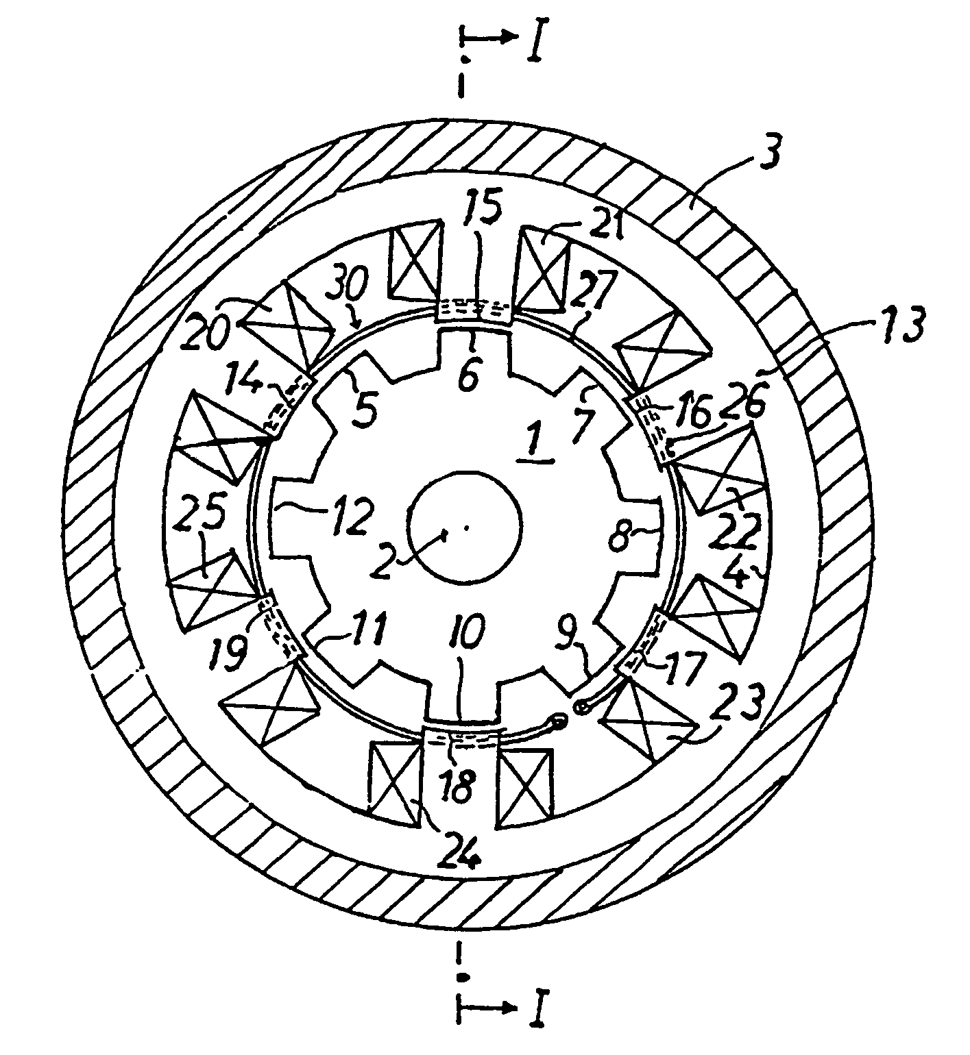
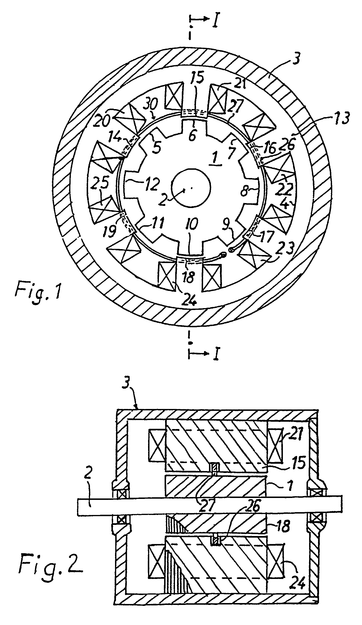
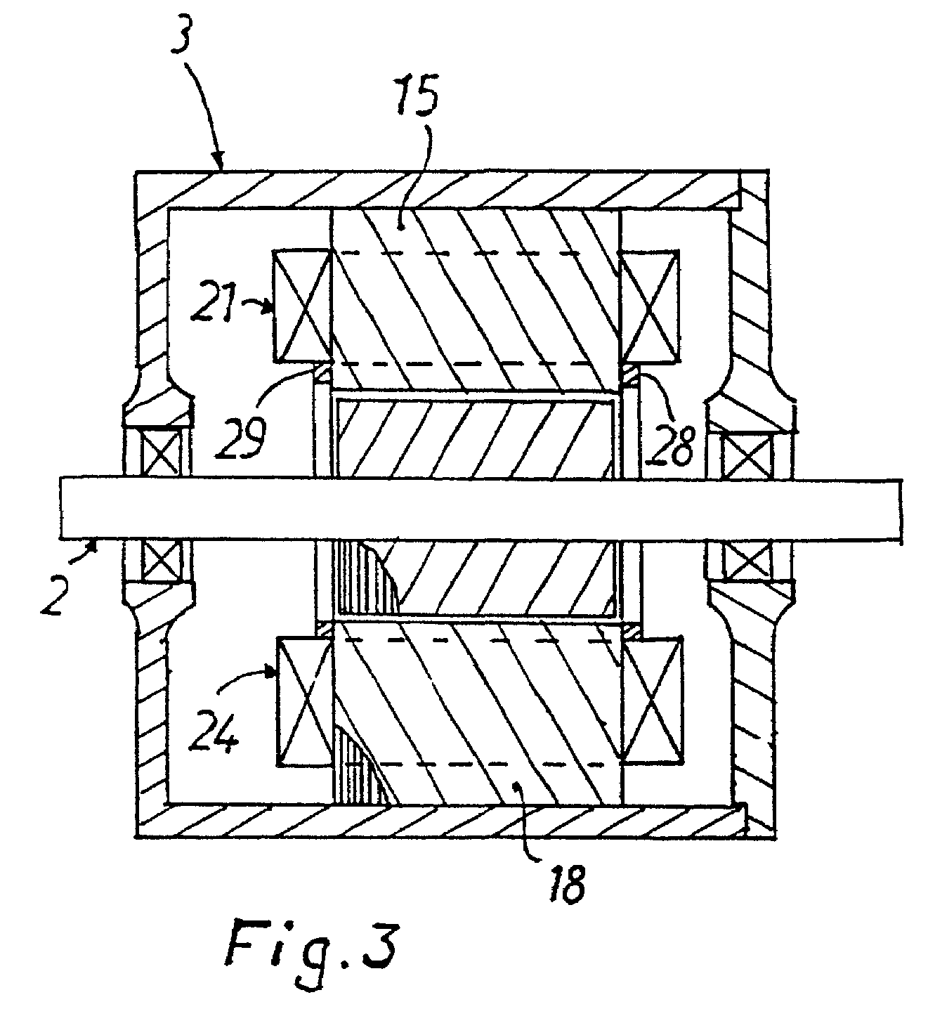
[0019]A reluctance motor has a rotor 1 fastened on a shaft 2 which is mounted for rotation in a housing 3. A stator 4 with a stator yoke is disposed coaxially with the rotor 1 within the housing 3 and fastened to the housing 3.

[0020]Rotor 1 and stator 4 are composed of laminated sheet iron. The rotor 1 has eight stamped poles 5, 6, 7, 8, 9, 10, 11, 12, which are arranged on the outer periphery at equal intervals from one another. Poles 5 to 12 are also referred to hereinafter as rotor teeth. The stator 4 has a hollow cylindrical yoke 13 from which six magnet poles or stator poles 14, 15, 16, 17, 18, 19 extend radially outward. The magnet poles 14 to 19, which are also referred to hereinafter as stator teeth, are arranged apart at equal intervals. The air gap between confronting stator and rotor poles is usually less than a millimeter. The magnet poles 14 to 19 have each parallel sides extending in the axial direction of the housing 3 and form one unit with the yoke 13.

[0021]Exciter ...


PUM


Abstract

A reluctance motor in which at least one snap ring engages the ends of the exciter coils remote from the stator yoke with radially outward acting spring force.

Description

BACKGROUND AND SUMMARY OF THE INVENTION[0001]This application claims the priority of German Application 19914943.7, filed Apr. 1, 1999, the disclosure of which is expressly incorporated by reference herein.[0002]The invention relates to a reluctance motor with at least two salient stator poles each provided with an exciter winding, and to a method for the manufacture of the stator of such a reluctance motor.[0003]Switching reluctance motors usually have numerous salient poles both in the stator and in the rotor. Each motor phase has at least one pair of stator poles lying diametrically opposite one another. An exciter winding is disposed on each stator pole. The two exciter windings on the stator poles are connected in series or in parallel. The stator and rotor poles consist of laminated sheet iron. When an exciter current is fed into the exciter windings, the stator poles are magnetized, so that magnetic attraction forces are exercised on the rotor, to thereby cause rotation.[0004...

Claims


Application Information

Patent Timeline
Patent Type & Authority Patents(United States)
IPC IPC(8): H02K1/24H02K3/52H02K19/06
CPCH02K3/522H02K19/06
Inventor BITSCHE, OTMARFUERST, MATTHIASHELLER, ANDREASKOENIG, WERNERMOCH, ANDREASMUELLER, DANIELNICKEL, ARMINZIEKER, ROLAND
Owner DAIMLER AG
Why Eureka
Try Eureka