Semi-automatic boxing machine

a semi-automatic boxing machine technology, applied in the field of products packaging, can solve the problems of reduced flexibility, serious instability, and extremely limited versatility of the boxing machine of the prior art, and achieve the effect of ensuring high versatility and flexibility standards

Inactive Publication Date: 2007-05-22
MARCHESINI GROUP SPA
View PDF15 Cites 17 Cited by
  • Summary
  • Abstract
  • Description
  • Claims
  • Application Information

AI Technical Summary

Benefits of technology

[0021]The object of the present invention is to avoid the above mentioned drawbacks by proposing a semiautomatic boxing machine, which assures high versatility and flexibility standards during the boxes filling, independently from the type of the treated products.
[0022]Another object of the present invention is to propose an extremely compact and strong machine, which allows an utmost reduction of the components and the corresponding maintenance and installation steps, and which assures high production rate in any operation conditions.
[0023]A further object of the present invention is to propose a machine, which assures the correct filling of the boxes, preventing any interfering and going out of the products during the introduction step.

Problems solved by technology

The versatility of the boxing machines of the prior art is extremely limited and they are characterized by a particularly reduced flexibility during the boxes filling, allowing only the introduction of pre-stratified and pre-piled up products, which results in serious instability of the latter during the transferring inside the boxes.
Moreover, it is very difficult to treat the products, which require a particular orientation inside the boxes, in particular in case of bottles, which must be positioned with the closing caps turned toward the upper flaps of the boxes.
Another drawback of the prior art machines lies undoubtedly in the presence at the work station of means for a first lateral turning of the boxes, so as to allow the filling of the latter, and for a second turning, with which the filled boxes are brought back to their original orientation, that is with the opening turned upwards.
The second turning is particularly difficult, because the stability of the products inside the boxes is not assured, which results in all the disadvantages connected to a probable going out or displacement of the products.
Moreover, the above turnings reduce strongly the machines production rate, prolonging the boxing time.
Further, it is difficult to use the semiautomatic boxing machines of the prior art for packaging particular types of products.

Method used


Image

  • Semi-automatic boxing machine
  • Semi-automatic boxing machine
  • Semi-automatic boxing machine

Examples


Embodiment Construction

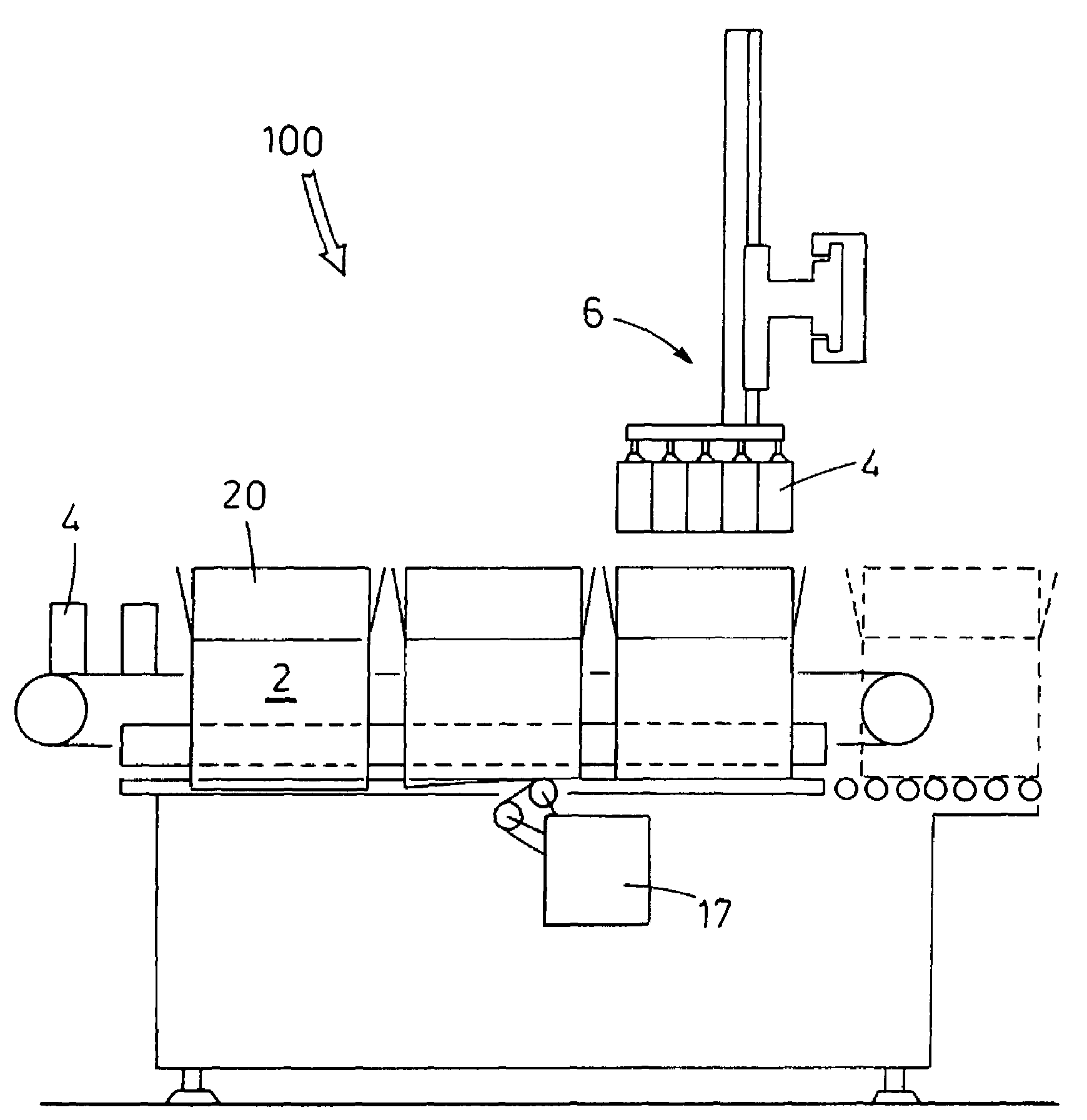
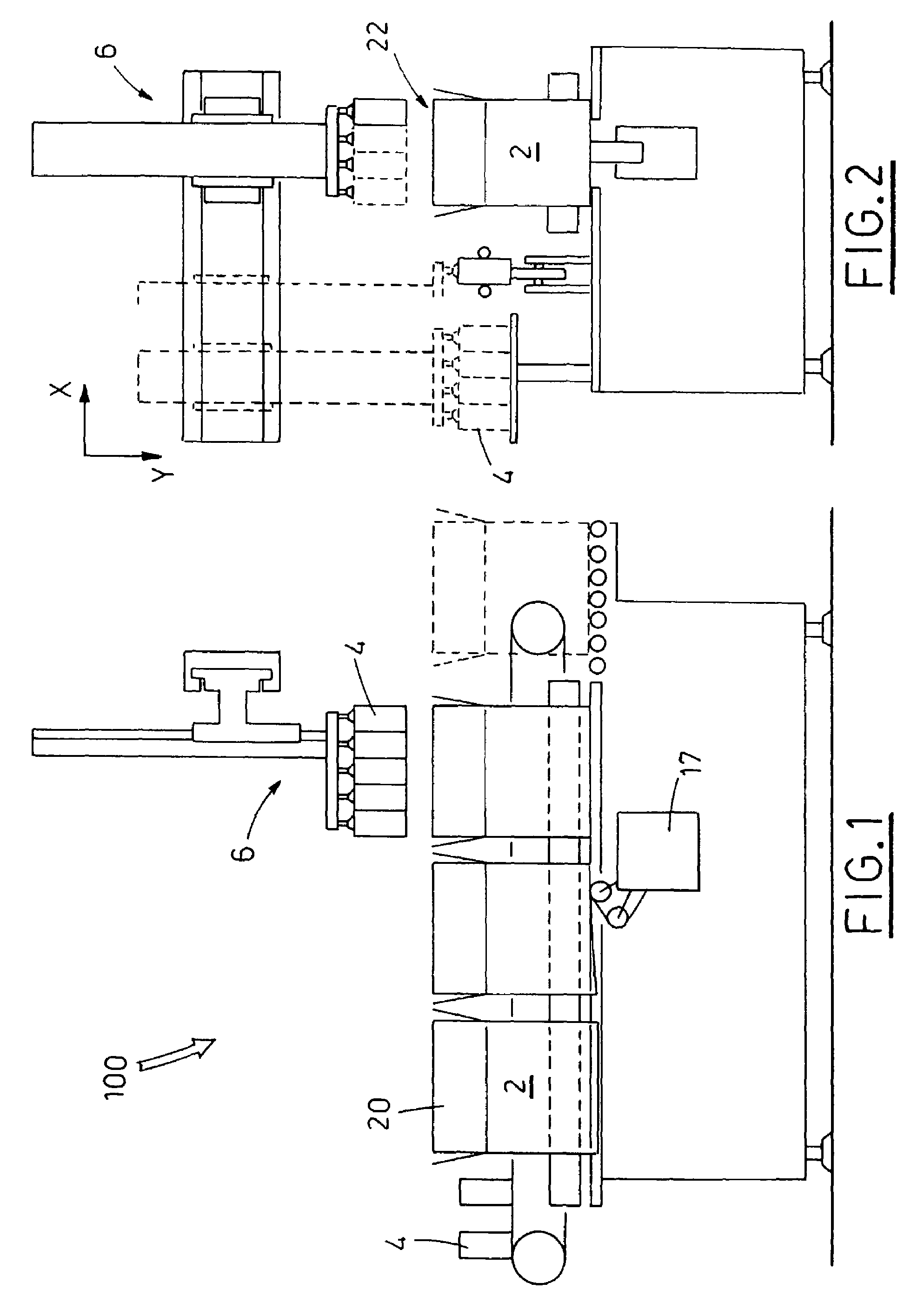
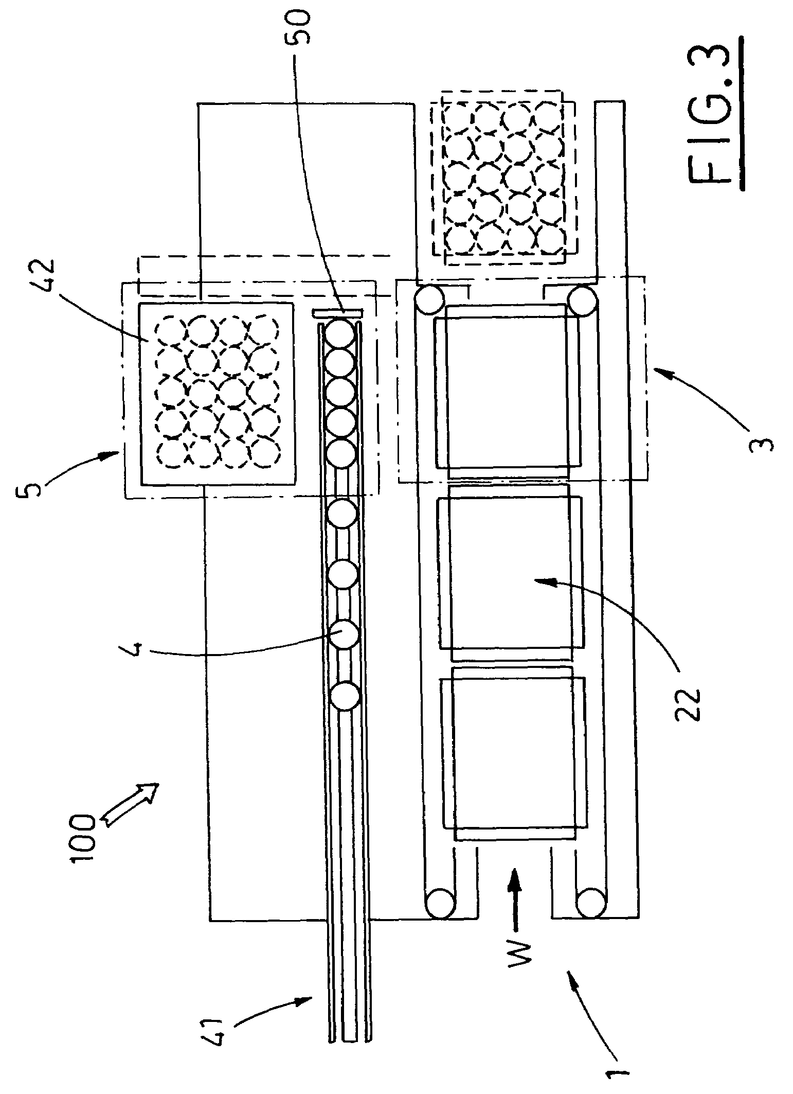
[0033]Regards the above drawings, the general reference number 100 indicates the proposed semiautomatic boxing machine, which includes a first conveying belt 1, receiving a plurality of erected blanks, substantially aligned boxes 2, and moving the latter to a work station 3 (FIG. 3).

[0034]Each box 2 is erected with its lower flaps folded, to define a closed bottom, and with its upper flaps 20 spread out and turned upwards, so as to define an inlet mouth 22 for the introduction of products 4.

[0035]In case of semiautomatic boxing machines, the blanks are erected manually by an operator, before their positioning on the first conveying belt 1.

[0036]Means 17 for taping the lower flaps of each box 2 are situated below the first conveying belt 1.

[0037]The proposed boxing machine 100 has also a second conveying belt 41, preferably operated continuously to receive a plurality of products 4 and moving the latter toward a station 5 for forming groups of products 4.

[0038]For example, the convey...


PUM

PropertyMeasurementUnit
angleaaaaaaaaaa
timeaaaaaaaaaa
angleaaaaaaaaaa

Abstract

In a semiautomatic boxing machine, a first conveyor receives and moves a plurality of erected boxes to a work station, while a second conveyor receives and moves a plurality of products to a station for forming groups of products. A manipulator picks up groups of products in the forming station and release them into corresponding boxes dwelling in the work station.

Description

FIELD OF THE INVENTION[0001]The present invention relates to packaging of products, with a particular reference to a semiautomatic boxing machine.DESCRIPTION OF THE PRIOR ART[0002]The semiautomatic boxing machines are fed manually by an operator, who previously erects the blanks to obtain the boxes.[0003]Generally, the operator folds the lower flaps of each blank, so as to close the bottom of a carton, leaving the upper flaps open, substantially spread out, to allow introduction of products.[0004]At the inlet of the boxing machines, the so obtained boxes, open in the upper part and with the closed bottom are positioned on a first conveying belt.[0005]The latter cooperates with associated means for automatic taping of the box lower flaps, in closing configuration.[0006]The first conveying belt feeds a work station, in which the boxes are turned laterally by 90°, so as to turn their openings facing the groups of products defined in a corresponding piling station.[0007]The piling stati...

Claims


Application Information

Patent Timeline
Patent Type & Authority Patents(United States)
IPC IPC(8): B65B35/30B65B5/10B65B21/18
CPCB65B5/105B65B21/18
Inventor BATTISTI, ANTONIO
Owner MARCHESINI GROUP SPA
Why Eureka
Try Eureka