Spade bit

a technology of spade bit and flat spade bit, which is applied in the field of spade bit, can solve the problems of increasing the pressure of the user to get the bit, affecting the quality of the finished product, and causing the operator to be injured, so as to reduce the chance of the operator injuring himself/herself, reduce the amount of vibration transferred to the user, and reduce the cost of production.

Active Publication Date: 2007-07-24
GREENLEE TEXTRON
View PDF26 Cites 11 Cited by
  • Summary
  • Abstract
  • Description
  • Claims
  • Application Information

AI Technical Summary

Benefits of technology

[0007]A primary object of the invention is to improve the ease of using an inexpensive spade bit by adding a feature to make it pull through the work piece like an auger bit.
[0008]Another primary object of the invention is to provide a self-feeding spade bit which is easy and fast to use.
[0009]A further object of the invention is to provide a spade bit which cleans the hole and permits easy removal of the spade bit from the hole after drilling.

Problems solved by technology

Also, as the spade bit begins to get dull, the user must apply more pressure to get the bit to cut chips.
Further, the flat spade bit has a tendency to vibrate and shake as it works.
The high axial force requirement causes much of the vibration to be transmitted to the user.
Another shortcoming of the spade bit is that since considerable axial force is applied, there is a potential for mishap when the hole is completed.
Such helical threads or circular grooves, however, have not been able to be provided on spade bits for two reasons: (1) the addition of helical threads or circular grooves to a spade bit would represent an unacceptable cost addition to spade bits; and (2) the typical spade bit is generally only 17 / 200″ to 19 / 200″ thick and, therefore, does not offer the same surface area for threads or grooves as a wood boring bit, which typically have a thickness of ¼″ to 3 / 10″.

Method used


Image

  • Spade bit
  • Spade bit
  • Spade bit

Examples


first embodiment

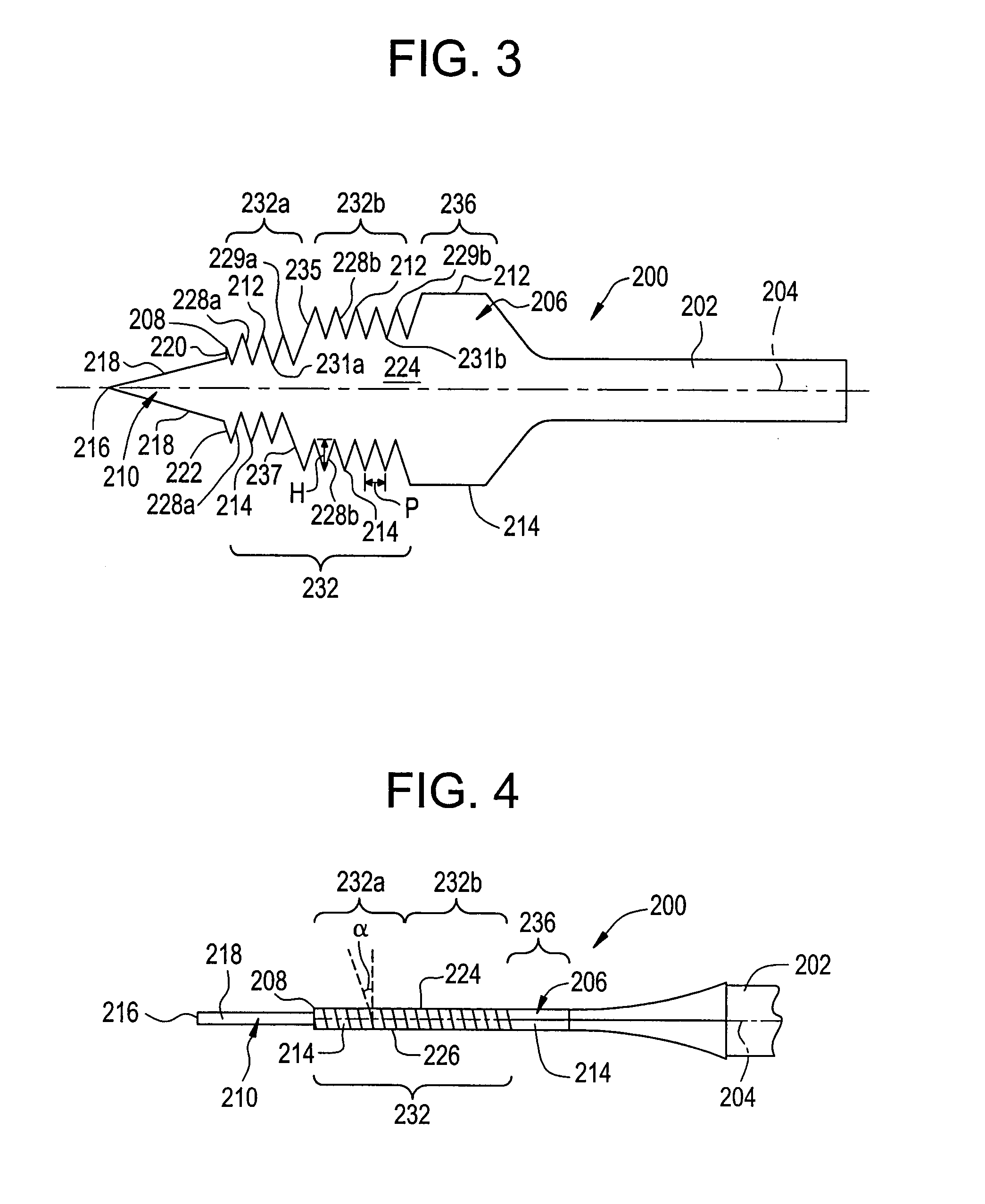
[0061]The spade bit 200 provides the same advantages over the standard spade bit as does the spade bit 100 of the first embodiment, but further provides the advantages of having the spade bit 200 feed itself with less engagement of the blade portion 206 with the work piece, i.e., ¼″ as opposed to ¾″. Further, the spade bit 200 has a distinct step in the first portion 232 of the blade portion 206 as the grooves 228a are provided on the first section 232a of the first portion 232 which has a diameter which is smaller than a diameter of the second section 232b of the first portion 232, where the grooves 228b are provided. As the first section 232a of the first portion 232 has a smaller diameter, the grooves 228a are able to provide more pulling with less resistive torque. The first section 232a of the first portion 232 requires less engagement with the workpiece before the spade bit 200 begins pulling itself through.

[0062]The second portion 236 is again provided in order to improve the...

fourth embodiment

[0075]Attention is invited to the spade bit 400 is illustrated in FIGS. 7-8. The spade bit 400 includes an elongated shaft 402 which defines a longitudinal axis 404. A generally flat blade portion 406 is joined to a forward end of the shaft 402. A rear end of the shaft 402, opposite the forward end, is received and held by a drill (not shown) during drilling operations.

[0076]A forward end 408 of the blade portion 406, opposite the forward end of the shaft 402, has a spur 410 which extends therefrom. The spur 410 is provided equidistant between a first side edge 412 of the blade portion 406 and a second side edge 414 of the blade portion 406. The spur 410 is used to center and to guide the spade bit 400 during drilling operations. The spur 410 is generally of a triangular or pyramidal configuration such that it comes to a point 416. The spur 410 also includes cutting edges 418 for removing wood or other material when the spade bit 400 is rotated in a predetermined direction of rotati...


PUM

PropertyMeasurementUnit
thicknessaaaaaaaaaa
thicknessaaaaaaaaaa
lead angleaaaaaaaaaa

Abstract

An embodiment of a spade bit has straight grooves at a lead angle of 4 to 8 degrees placed on flat edges of the spade bit. In an alternative embodiment, a spade bit has two steps of straight grooves at a lead angle of 4 to 8 degrees placed on flat edges of the spade bit. In other alternative embodiments, a spade bit has tapered flat edge which have straight grooves at a lead angle of 4 to 8 degrees placed thereon. The straight grooves on the flat edges of the spade bits allow the spade bit to pull itself through the workpiece with a minimal amount of penetration. The flat edges of the spade bit may also have cutting surfaces for cleaning the hole and permitting the easy removal of the spade bit from the hole after drilling.

Description

CROSS-REFERENCE[0001]This patent application claims the benefit of domestic priority of U.S. Provisional Application Ser. No. 60 / 513,127, filed Oct. 21, 2003, and entitled “Spade Bit”.BACKGROUND OF THE INVENTION[0002]The present invention relates to a spade bit.[0003]Spade bits are generally flat, inexpensive bits having a thickness of generally between 17 / 200″ and 19 / 200″, which are commonly used in the construction trade for making clearance holes for electrical and plumbing purposes. Spade bits are also commonly used for drilling bolt holes in deck timbers (4×4 and 6×6).[0004]Spade bits, however, have a number of shortcomings. For instance, spade bits require more axial pressure than a twist drill. Also, as the spade bit begins to get dull, the user must apply more pressure to get the bit to cut chips. The axial force requirement also increases as the depth of the hole increases. Further, the flat spade bit has a tendency to vibrate and shake as it works. The high axial force req...

Claims


Application Information

Patent Timeline
Patent Type & Authority Patents(United States)
IPC IPC(8): B27G15/00B23B51/00
CPCB23B51/0009B27G15/00B23B2251/14B23B2251/248Y10T408/909Y10T408/9065B23B2251/406B23B51/00035
Inventor NORDLIN, WILLIAM F.
Owner GREENLEE TEXTRON
Why Eureka
Try Eureka