Exciting device

a technology of exciting device and display device, which is applied in the direction of transducer diaphragm, instruments, and details of portable computers, etc., can solve the problems of increasing the number of parts, difficult to miniaturize the electronic apparatus, and inability to provide other apparatuses, so as to simplify the structure of the exciting device and reduce the number of parts , the effect of easy vibrating the exciting member

Inactive Publication Date: 2007-10-16
ALPS ALPINE CO LTD
View PDF9 Cites 21 Cited by
  • Summary
  • Abstract
  • Description
  • Claims
  • Application Information

AI Technical Summary

Benefits of technology

[0010]It is another object of the present invention to provide a display device on the backside of which a display panel is provided, the display device capable of generating sound from the surface of the display panel and of being manufactured at a low price.
[0036]As mentioned above, since the area of the exciting member is smaller than the area of the transparent substrate, it is preferable that the elastic coefficient of the exciting member due to bending be smaller than the elastic coefficient of the transparent substrate due to bending, on condition that the area of the exciting member is equal to the area of the transparent substrate, and it is more preferable that the exciting member be longitudinal, the exciting member vibrates due to the vibration applied by the vibration generating means with a large amplitude and the vibration is transmitted to the transparent substrate. It is possible to vibrate the transparent substrate with large amplitude due to the transmission of the vibration and to thus obtain a loud sound from the transparent substrate.

Problems solved by technology

Since it is not possible to mount a speaker in a small portable electronic player, a user listens to music by connecting a headphone or an external connection speaker to the electronic player.
However, when the vibration plate of such a size is mounted in the electronic apparatus, it is difficult to miniaturize the electronic apparatus.
Therefore, due to the exciters and the small panels, it is not possible to provide other apparatuses such as a display panel in the hind portion of the large panel.
In addition, when the plurality of exciters is mounted, the number of parts increases to thus increase manufacturing costs.

Method used


Image

  • Exciting device
  • Exciting device
  • Exciting device

Examples


Embodiment Construction

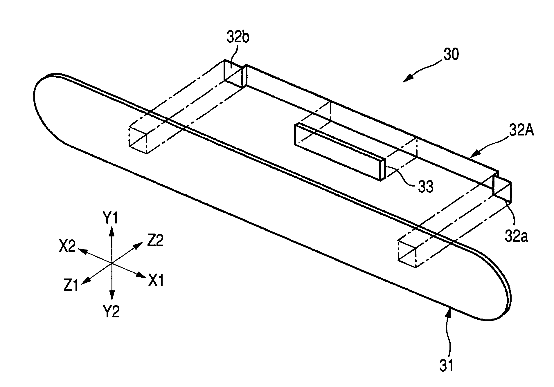
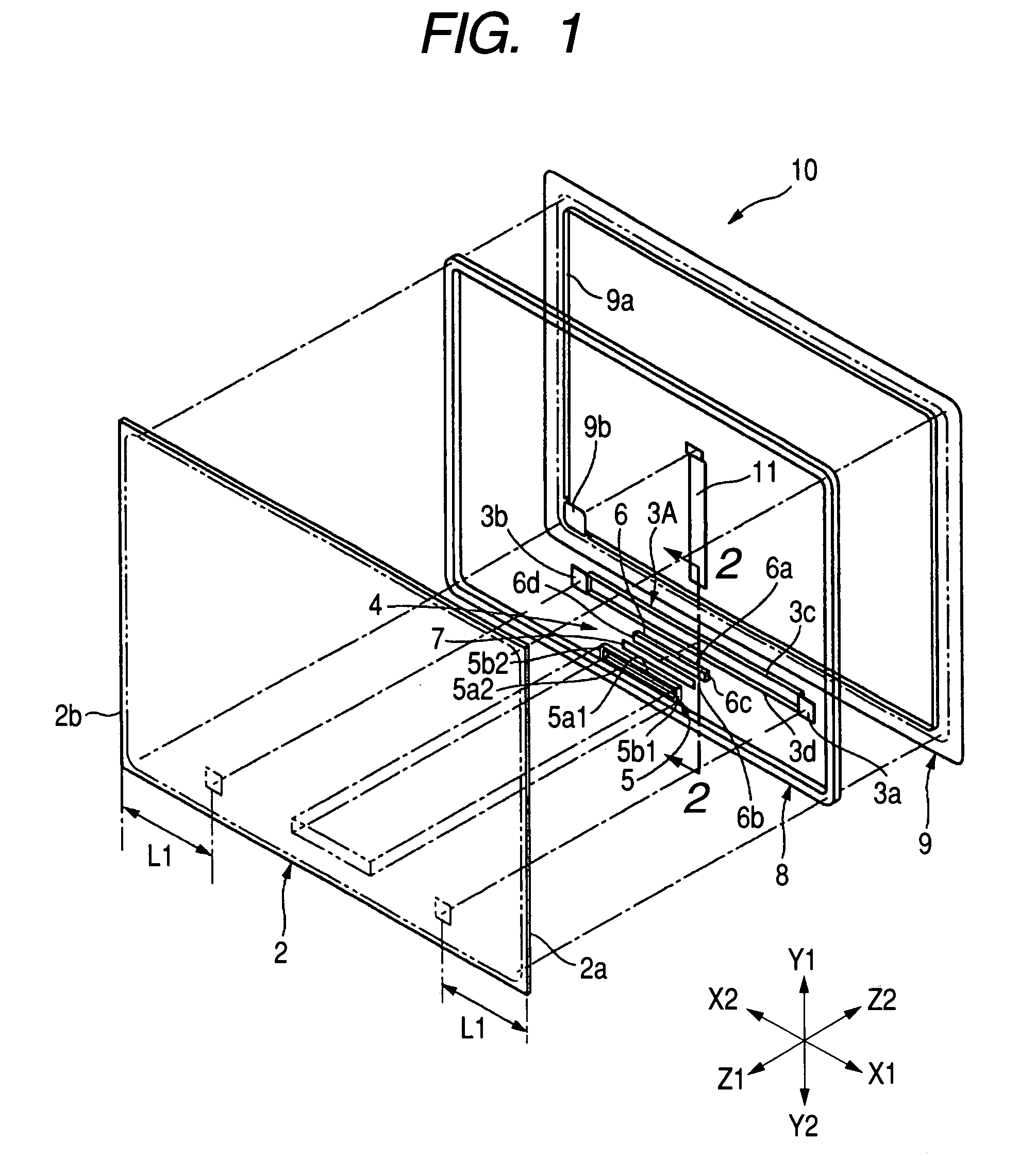
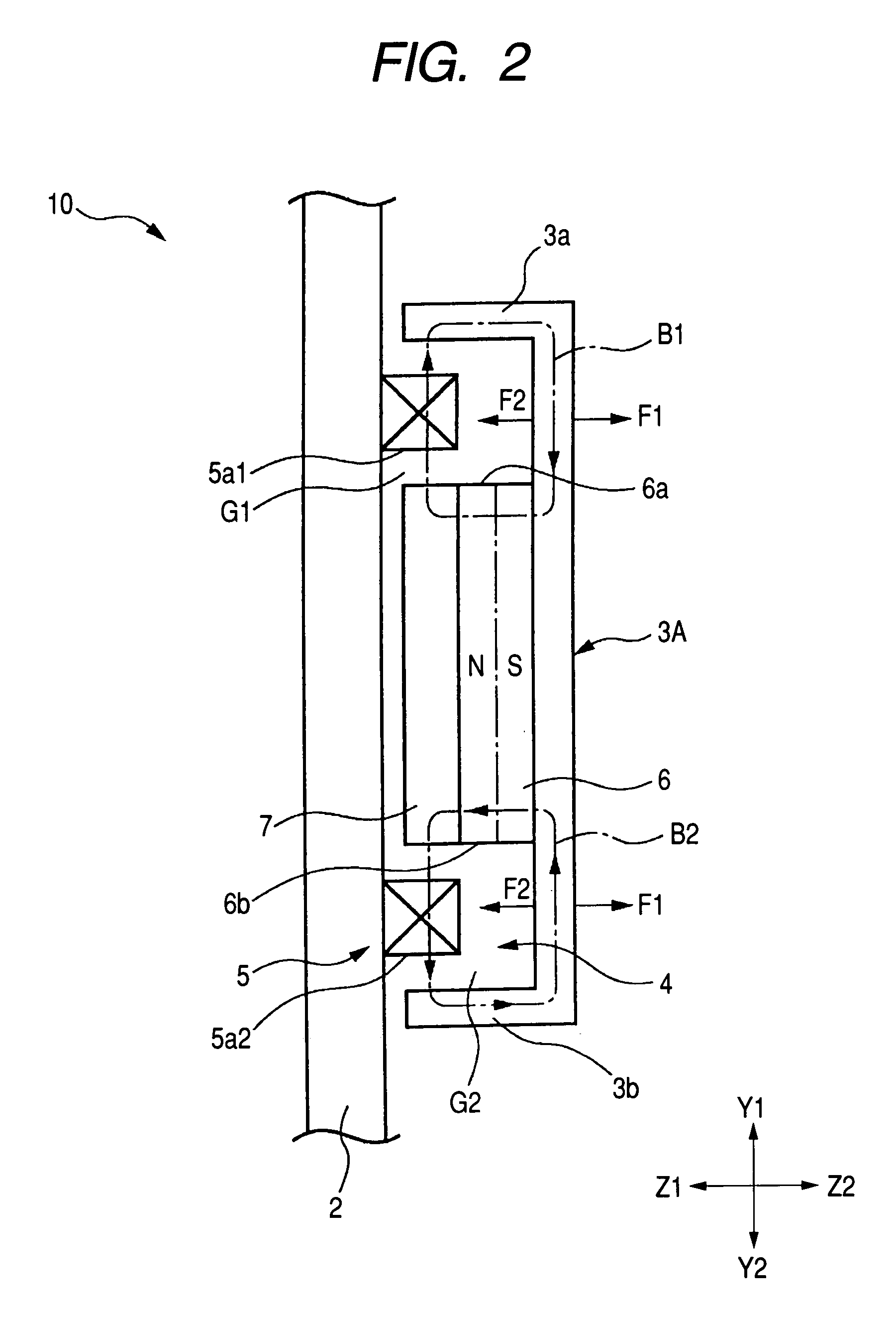
[0097]FIG. 1 is an exploded perspective view illustrating an example of an exciting device capable of being mounted on the surface of a display panel. FIG. 2 is a sectional view taken along the line 2-2 of FIG. 1.

[0098]An exciting device 10 illustrated in FIG. 1 includes a transparent substrate 2, an exciting member 3A, and vibration generating means 4. The transparent substrate 2 is a square substrate made of a material having a high degree of transparency such as acryl resin, polycarbonate, and glass.

[0099]The exciting member 3A is made of a magnetic material such as iron and ferrite and has an area much less than the area of the transparent substrate 2. The exciting member 3A is on the side Y2 of the transparent substrate 2 and is mounted from the side Z2. When the length is in the direction X and the width is in the direction Y, the exciting member 3A is formed to be longitudinal so that the length is larger than the width.

[0100]Fixing portions 3a and 3b fixed to the transparent...


PUM


Abstract

An exciting device capable of producing sound by sound-producing vibration body of a main body of an apparatus is provided. An exciting member 32A thin and long in the direction X is provided on a vibration substrate 31 thin and long in the direction X. Both ends of the exciting member 32A are fixed to the vibration substrate 31. Further, a piezoelectric element 33 that functions as vibration generating means is provided in the middle in the direction X of the exciting member 32A. The vibration substrate 31 is directly or indirectly fixed to the sound-producing vibration body. Vibration of the exciting member 32A is transmitted to the sound-producing vibration body through the vibration substrate 31 so that the sound-producing vibration body produces sound.

Description

[0001]This application claims the benefit of priority to Japanese Patent Application Nos. 2003-146840, 2003-146848 and 2003-146870, herein incorporated by reference.BACKGROUND OF THE INVENTION[0002]1. Field of the Invention[0003]The present invention relates to a display device in which sound is produced by the surface of a display panel.[0004]2. Description of the Related Art[0005]A panel-shaped speaker is described in a patent document 1 described below. In the patent document 1, on a large panel, panels smaller than the large panel are provided in order to overlap each other. Exciters are provided in the small panels. In the speaker, when the exciters are driven, the small panels vibrate and, at the same time, the vibration of the small panels is transmitted to the large panel so that the large panel and the small panels produce sound.[Patent Document 1][0006]PCT Japanese Translation Patent Publication No. 2002-505814[0007]Since it is not possible to mount a speaker in a small po...

Claims


Application Information

Patent Timeline
Patent Type & Authority Patents(United States)
IPC IPC(8): H04R11/02H04R9/06G06F1/16H04M1/03H04R7/04H04R17/00
CPCG06F1/1616G06F1/1626G06F1/1637G06F1/1688H04R2499/15H04R7/045H04R17/00H04R2440/05H04M1/03
Inventor SUZUKI, KATSUTOSHISAITO, KOICHIHORINO, TAKENOBUHIGUCHI, SHINICHISUZUKI, KATSUJIMITSUISHI, TETSUYA
Owner ALPS ALPINE CO LTD
Why Eureka
Try Eureka