Visual code system for camera-equipped mobile devices and applications thereof

a mobile device and code technology, applied in still video cameras, instruments, electromagnetic radiation sensing, etc., can solve the problems of limited mobile devices produced for the general public that contain integrated laser-based scanners, curtailed their expansion into the mobile marketplace, and few mobile devices that contain mobile devices attached to scanners. , to achieve the effect of simplifying the interaction with the mobile device itself, short interaction time, and simplifying the interaction with the mobile devi

Inactive Publication Date: 2007-11-20
ROHS MICHAEL
View PDF91 Cites 173 Cited by
  • Summary
  • Abstract
  • Description
  • Claims
  • Application Information

AI Technical Summary

Benefits of technology

[0010]Enhancing mobile devices in this manner is promising, because they are in constant reach of their users and are thus available in many everyday situations. They provide continuous wireless connectivity, and models with integrated cameras are becoming more and more popular. The ability to detect objects in the user's immediate vicinity strengthens the role of mobile phones in m-commerce, education, and gaming scenarios. Additionally, it offers a natural way of interaction and makes data entry more convenient.
[0023]A further object of the present invention is to provide an application wherein the visual code system is used in conjunction with printed forms for convenient data entry.

Problems solved by technology

However, mobile devices with attached scanners possess some drawbacks which have curtailed their expansion into the mobile marketplace.
First, there are few mobile devices produced for the general public that contain integrated laser-based scanners.
The additional scanning equipment also adds size and weight to the mobile device, thereby reducing its mobility.
Decoding barcode images from digital cameras included in mobile devices presents several difficult problems.
These problems go well beyond the challenges addressed in commercial barcode readers.

Method used


Image

  • Visual code system for camera-equipped mobile devices and applications thereof
  • Visual code system for camera-equipped mobile devices and applications thereof
  • Visual code system for camera-equipped mobile devices and applications thereof

Examples


Embodiment Construction

)

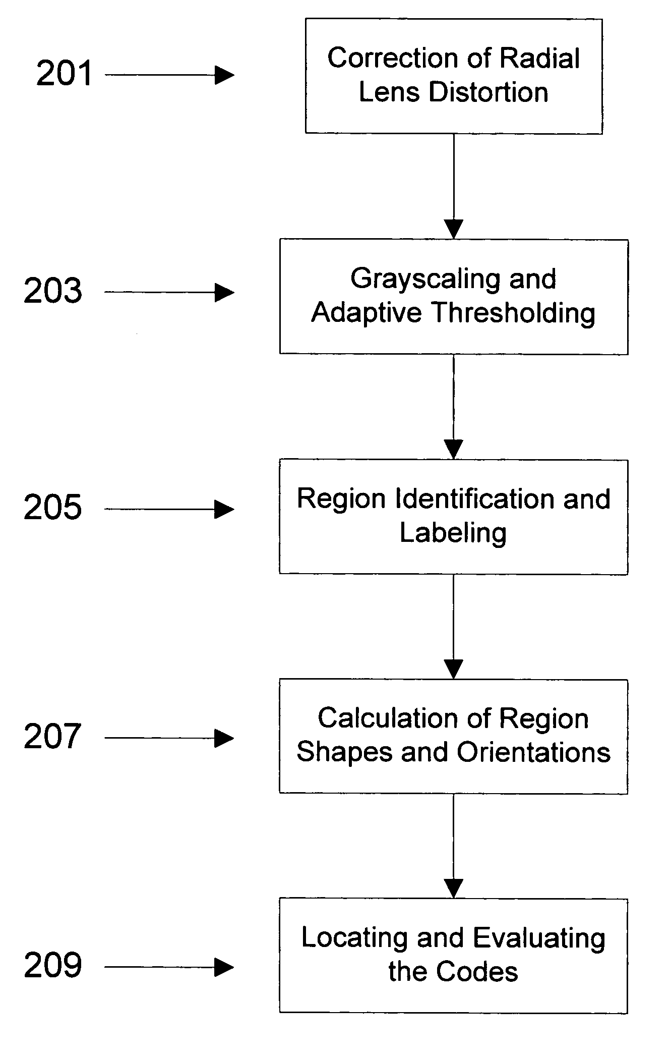
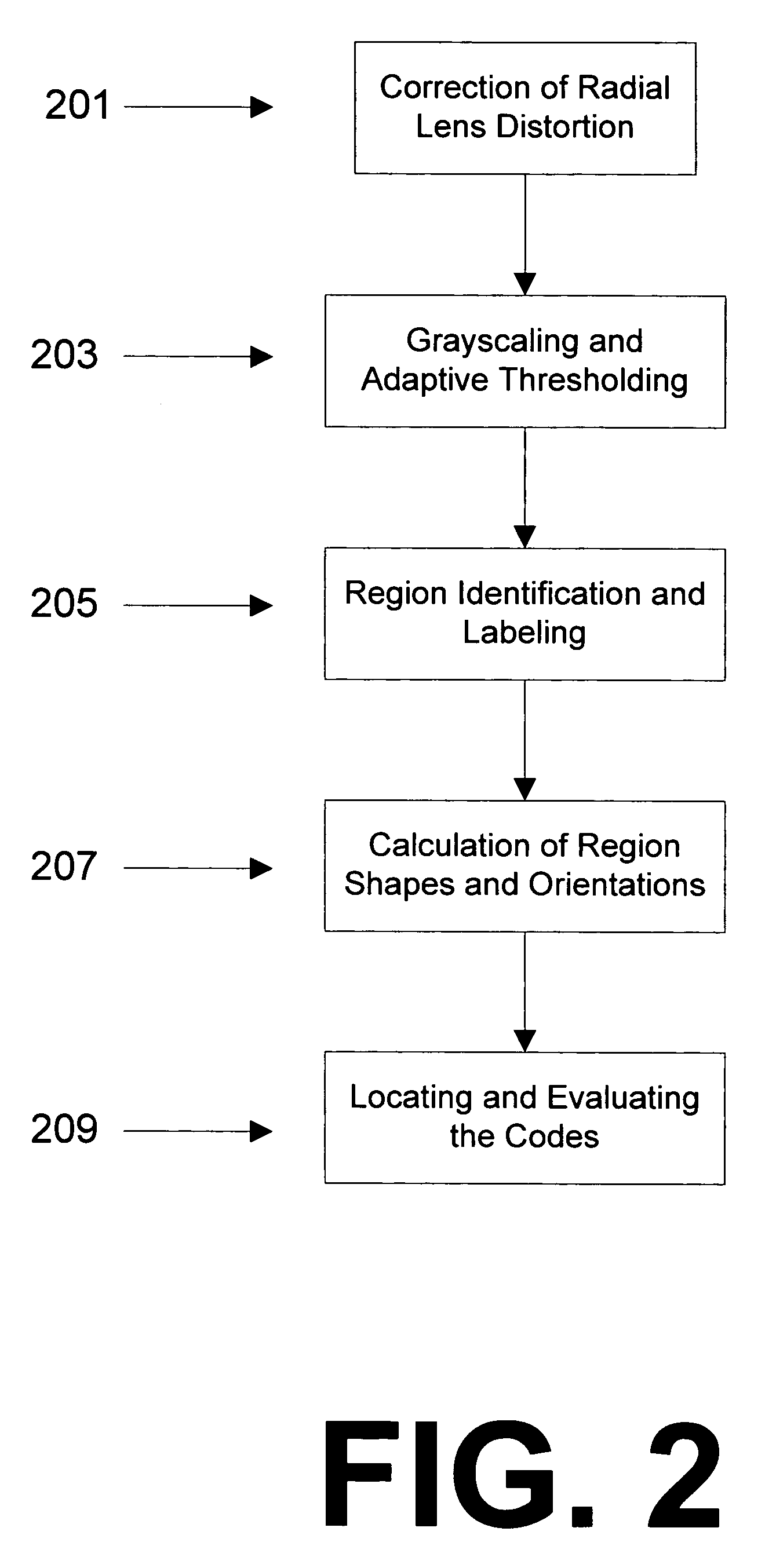
[0031]The following presents a detailed description of a preferred embodiment (as well as some alternative embodiments) of the present invention. However, it should be apparent to one skilled in the art that the described embodiment may be modified in form and content to be optimized for a wide variety of situations.

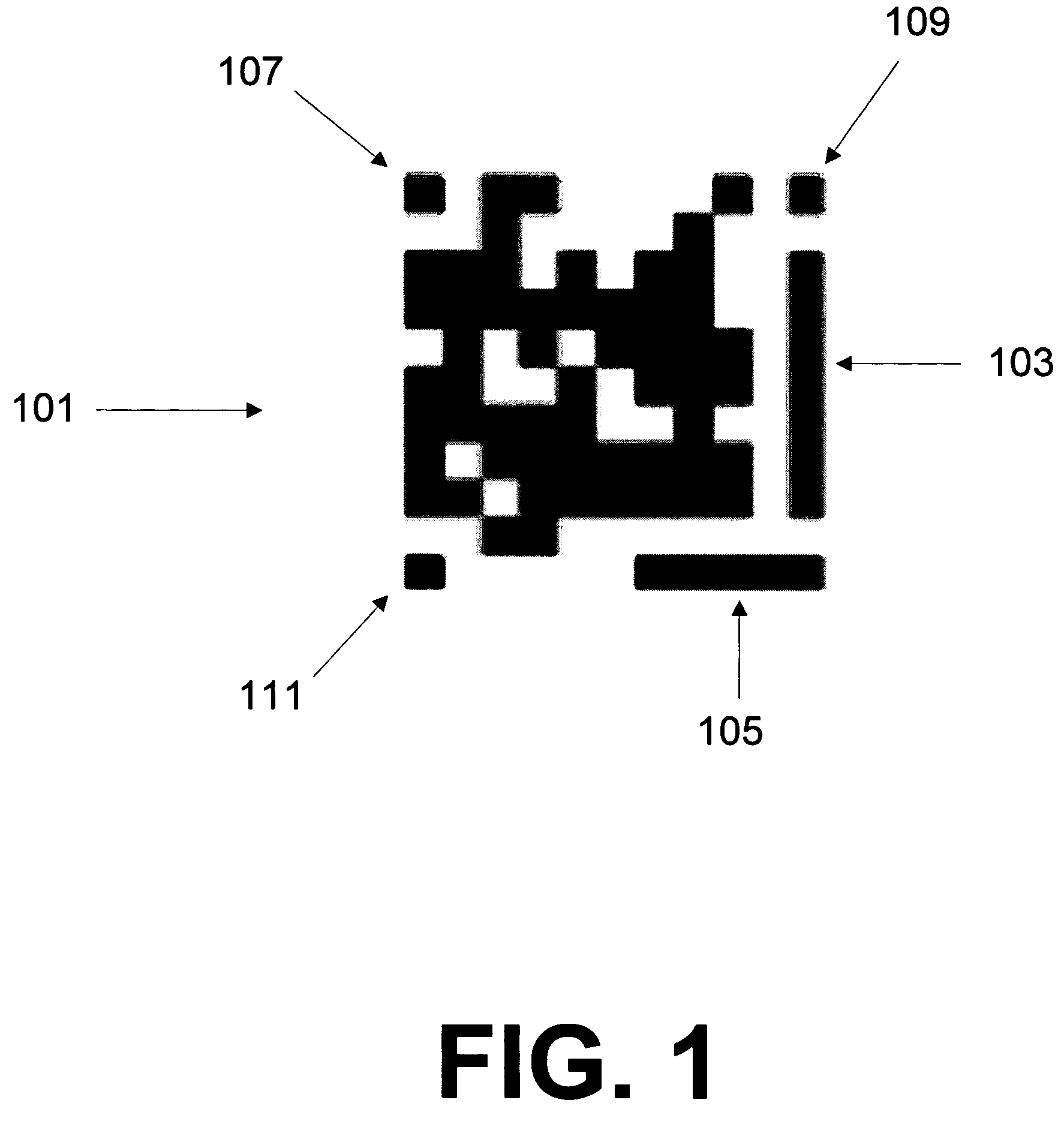
[0032]With reference first to FIG. 1, shown is an example of visual code 101 utilized in the present invention. Visual code 101 consists of large guide bar 103 and small guide bar 105 for determining the location and orientation of visual code 101, three cornerstones 107, 109, and 111, for detecting distortion and the data area with the actual code bits. The displayed version of visual code 101 has a capacity of 83 bits, but its design is generic and suitable for extension to a larger number of bits. Visual code 101 can be reliably located even in a low quality image which is small and tilted.

[0033]Visual code 101 may be printed utilizing either standard ink or infrared...


PUM


Abstract

A visual code system wherein camera-equipped mobile phones (or similar devices, such as wireless PDAs) are used to identify and decode images that contain one or more “visual codes.” By recognizing a code tag, the device can determine a bit pattern or an integer number encoded in the tag (the code value), the targeted object or image element, as well as additional parameters, such as the viewing angle of the camera. Code recognition is performed on the mobile device itself. When the mobile device is equipped with a wireless communication channel, it can be used to retrieve online content or to access information on the Internet based on the sensed code and its parameters. The retrieved content can then be presented on the mobile device.

Description

CROSS-REFERENCE TO RELATED APPLICATIONS[0001]This application claims the benefit of Provisional Application Ser. No. 60 / 563,669 filed Apr. 20, 2004.FIELD OF THE INVENTION[0002]The present invention relates to the field of decoding machine readable codes utilizing camera-equipped mobile devices. More specifically, the present invention discloses a proprietary visual code which is capable of being decoded and utilized by virtually any camera-equipped mobile device.BACKGROUND OF THE INVENTION[0003]Barcodes have been utilized for identifying and pricing objects for more than thirty years. Most typically, barcodes are used in retail to identify the item of merchandise. For example, a gallon of milk may contain a barcode that, when scanned, will notify the cashier of the price of the milk.[0004]Yet in recent years, barcodes have acquired new purposes as computers and barcode scanners have become more portable. The circuitry required to scan a conventional one-dimensional barcode can now b...

Claims


Application Information

Patent Timeline
Patent Type & Authority Patents(United States)
IPC IPC(8): G06K5/04G06K7/10G06K9/32H04M1/66H04M1/72403H04N1/107H04N1/32
CPCH04M1/72522H04N1/32133H04M2250/52H04N2201/3269H04N2101/00H04N1/107H04M1/72403
Inventor ROHS, MICHAEL
Owner ROHS MICHAEL
Why Eureka
Try Eureka