Image display apparatus, display unit driver and image display method for the same

a technology of image display and driver, which is applied in the direction of instruments, television systems, and television system scanning details, etc., can solve the problems of difficulty in achieving stable enhancement of contrast, coupled, and difficulty in maintaining the luminance level of luminance signals, so as to achieve high contrast stably

Active Publication Date: 2008-02-19
MAXELL HLDG LTD
View PDF15 Cites 8 Cited by
  • Summary
  • Abstract
  • Description
  • Claims
  • Application Information

AI Technical Summary

Benefits of technology

[0005]In view of the related conventional technology, the present invention is intended to obtain stable high-contrast performance based on stable maintenance of luminance levels in an image display apparatus. That is to say, the present invention has been made in consideration of the problems associated with the above conventional technology, and an object of the invention is to provide a technology that allows image display with high picture quality.
[0006]In order to attain the above object, in the image display technology of the present invention, video contrast is adjusted by feeding back the maximum luminance level information and average luminance level (=average picture level: APL) information relating to a digital luminance signal and changes the gain of the luminance signal. Also, control is conducted to ensure that when the average luminance level (APL) detected from the above-mentioned feedback system is higher than the upper-limit value of a previously set reference range, the illuminance of the light applied from a backlight to the screen of a display unit is increased, and that when the average luminance level is lower than the lower-limit value of the reference range, the illuminance of the backlight is reduced.
[0008]According to the present invention, high contrast can be stably obtained.

Problems solved by technology

Difficulty is therefore expected to occur in maintaining the luminance level of the luminance signal stably.
Difficulty in achieving stable enhancement of contrast, coupled with the above, is also expected to arise.

Method used


Image

  • Image display apparatus, display unit driver and image display method for the same
  • Image display apparatus, display unit driver and image display method for the same
  • Image display apparatus, display unit driver and image display method for the same

Examples


Embodiment Construction

[0017]Preferred embodiments of the present invention are described below with reference to the accompanying drawings.

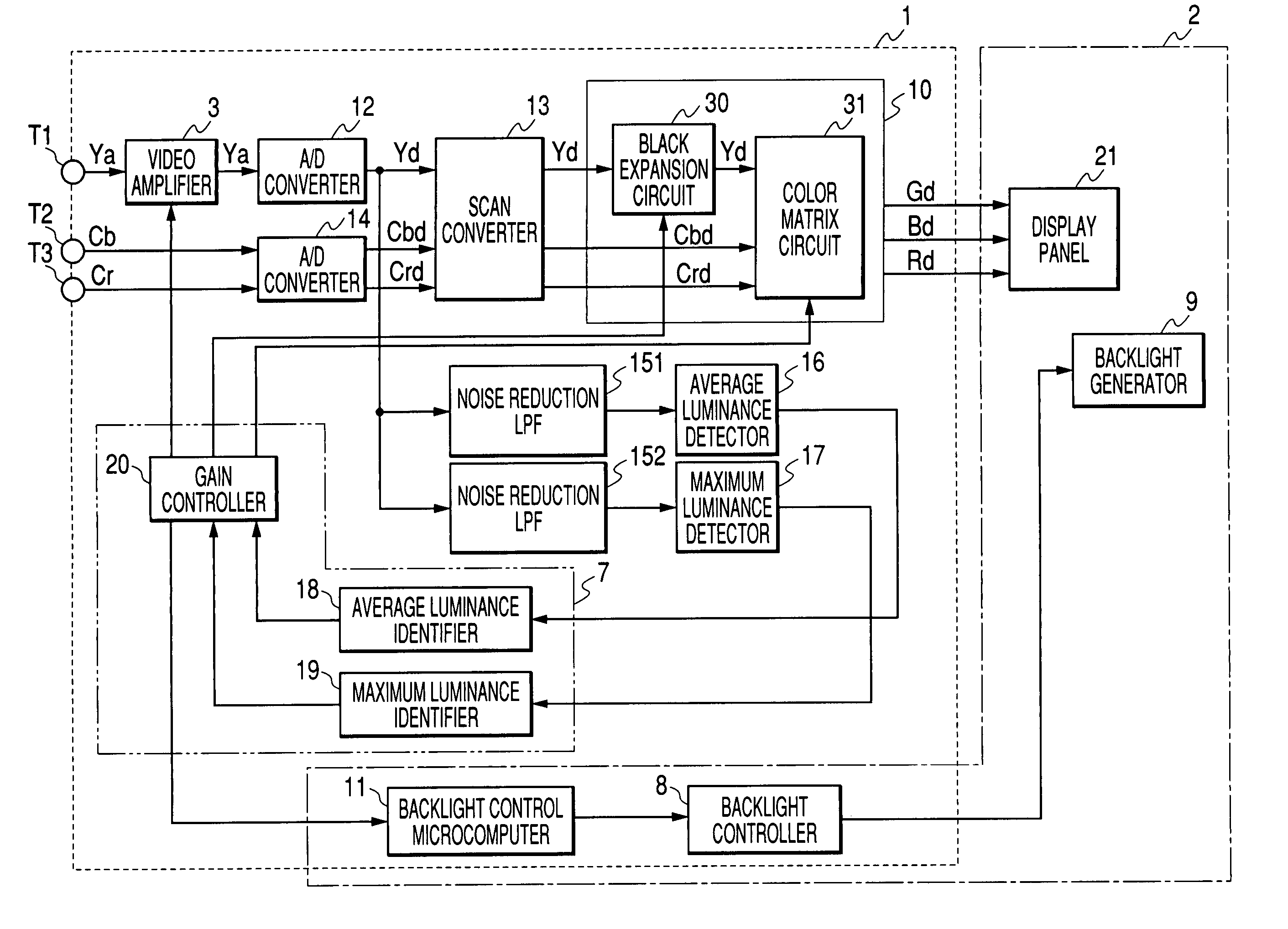
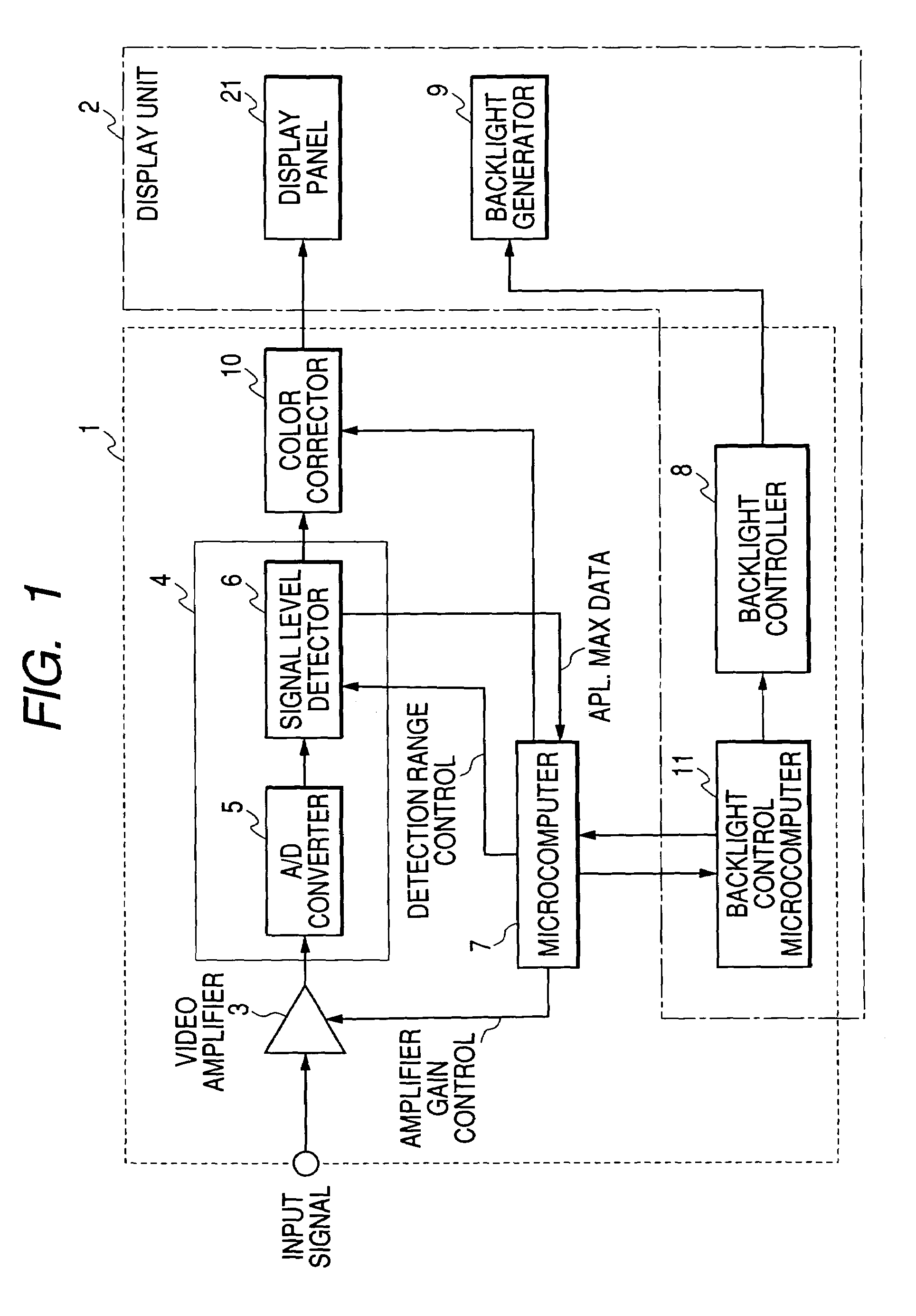
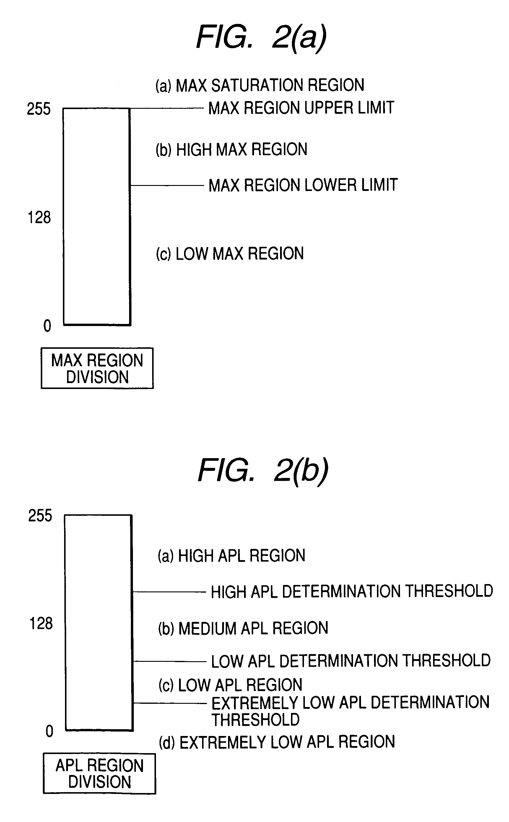
[0018]FIGS. 1 to 7 are diagrams explaining a first embodiment of the present invention. FIG. 1 is a basic configuration diagram of an image display apparatus according to the first embodiment of the invention, and FIGS. 2A and 2B are explanatory diagrams that show luminance region division of a maximum luminance level and that of an average luminance level, respectively. FIGS. 3A and 3B are diagrams showing the relationships between divided luminance regions and gain control, and FIG. 4 is an explanatory diagram of the gain control range in contrast adjustment. FIG. 5 is a diagram showing the relationship between an average luminance level and an amount of backlight correction, FIG. 6 is a diagram showing an example of circuit composition of the image display apparatus according to the first embodiment, and FIG. 7 is a diagram explaining the effects obtained in the fi...


PUM

PropertyMeasurementUnit
luminanceaaaaaaaaaa
illuminanceaaaaaaaaaa
average luminance levelaaaaaaaaaa

Abstract

An object of the present invention is to provide an image display technology with which high contrast can be stably obtained.In order to achieve the above object, the present invention changes the gain of a digital luminance signal by feeding back information on maximum and average luminance levels of the luminance signal, adjusts image contrast, and in accordance with the average luminance level detected from the feedback system, controls the illuminance of the backlight applied to a display unit. The control increases the illuminance of the backlight when the detected average luminance level is higher than the upper-limit value of a previously set reference range, and reduces the illuminance when the detected average luminance level is lower than the lower-limit value of the reference range.

Description

CLAIM OF PRIORITY[0001]The present application claims priority from Japanese application serial no. P2003-303252, filed on Aug. 27, 2003, the content of which is hereby incorporated by reference into this application.BACKGROUND OF THE INVENTION[0002]The present invention relates to a technology for converting television signals and the analog video signals input from a personal computer or the like, into digital video signals, and thus displaying an image on a display unit such as a liquid-crystal panel.[0003]Technologies related to the present invention include the technology disclosed in, for example, Japanese Patent Laid-open No. 5-66501 (Document 1). Document 1 describes a projection-type liquid-crystal display apparatus constructed so that it detects an average luminance of video signals per screen, modulates in response to the signal of the detected average luminance the video signal voltage to be applied to a liquid-crystal panel, and changes the luminance of a light source.S...

Claims


Application Information

Patent Timeline
Patent Type & Authority Patents(United States)
IPC IPC(8): G09G3/36G02F1/133G09G3/18G09G3/20G09G3/34G09G5/04H04N5/66H04N5/74H04N9/12
CPCG09G3/3406H04N9/3155G09G3/2092G09G5/04G09G2360/16
Inventor AOKI, HIROSHIHASEGAWA, RYOSAKAMOTO, HIROFUMITAKATA, HARUKITSURU, YASUTAKA
Owner MAXELL HLDG LTD
Why Eureka
Try Eureka