Modulation light source, image display apparatus including the same, and method of driving modulation light source

a technology of modulation light and image display, which is applied in the direction of optical resonator shape and construction, semiconductor lasers, instruments, etc., can solve the problem of impaired linearity of gradation expression, and achieve the effect of easy realization of high-resolution gradation level expression of shg ligh

Inactive Publication Date: 2008-05-20
CANON KK
View PDF9 Cites 12 Cited by
  • Summary
  • Abstract
  • Description
  • Claims
  • Application Information

AI Technical Summary

Benefits of technology

[0006]An object of the present invention is to solve such problems, and more specifically to provide a modulation light source capable of maintaining thermal stabilities of a DBR laser and a light wavelength conversion device, that is, easily realizing high-resolution gradation level expression of SHG light without depending on a pattern of a PWM signal.
[0009]According to the present invention, it is possible to provide a modulation light source capable of easily realizing the high-resolution gradation level expression of the SHG light. In addition, according to the present invention, it is possible to provide a modulation light source that maintains the thermal stabilities of the DBR laser and the light wavelength conversion device, that is, that does not depend on the pattern of the PWM signal.

Problems solved by technology

However, the inventors of the present invention found a problem in that such a technique requires a high-precision analog circuit in order to realize high-resolution gradation level expression and the linearity of gradation expression is impaired in the case where a peak point of conversion efficiency of the SHG light is deviated due to a change in environmental temperature, or the like.
In this case, there is a problem in that a temperature of the DBR laser 1010 and a temperature of the light wavelength conversion device 1020 depend on the pattern of the PWM signal.

Method used


Image

  • Modulation light source, image display apparatus including the same, and method of driving modulation light source
  • Modulation light source, image display apparatus including the same, and method of driving modulation light source
  • Modulation light source, image display apparatus including the same, and method of driving modulation light source

Examples


first embodiment

[0026]Hereinafter, a more specific example according to a first embodiment of the present invention will be described with reference to the drawings.

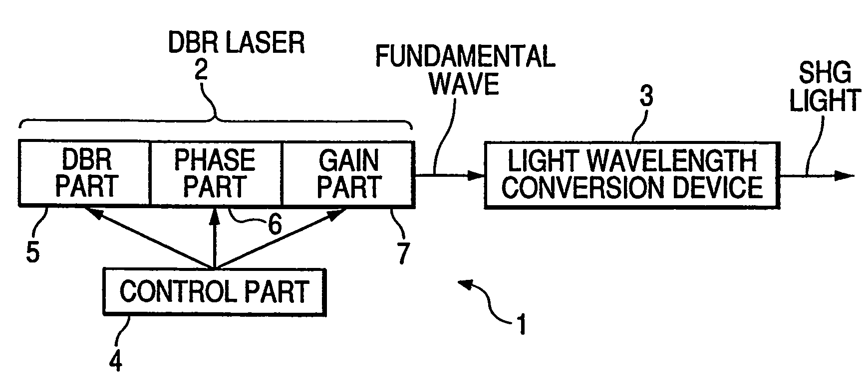
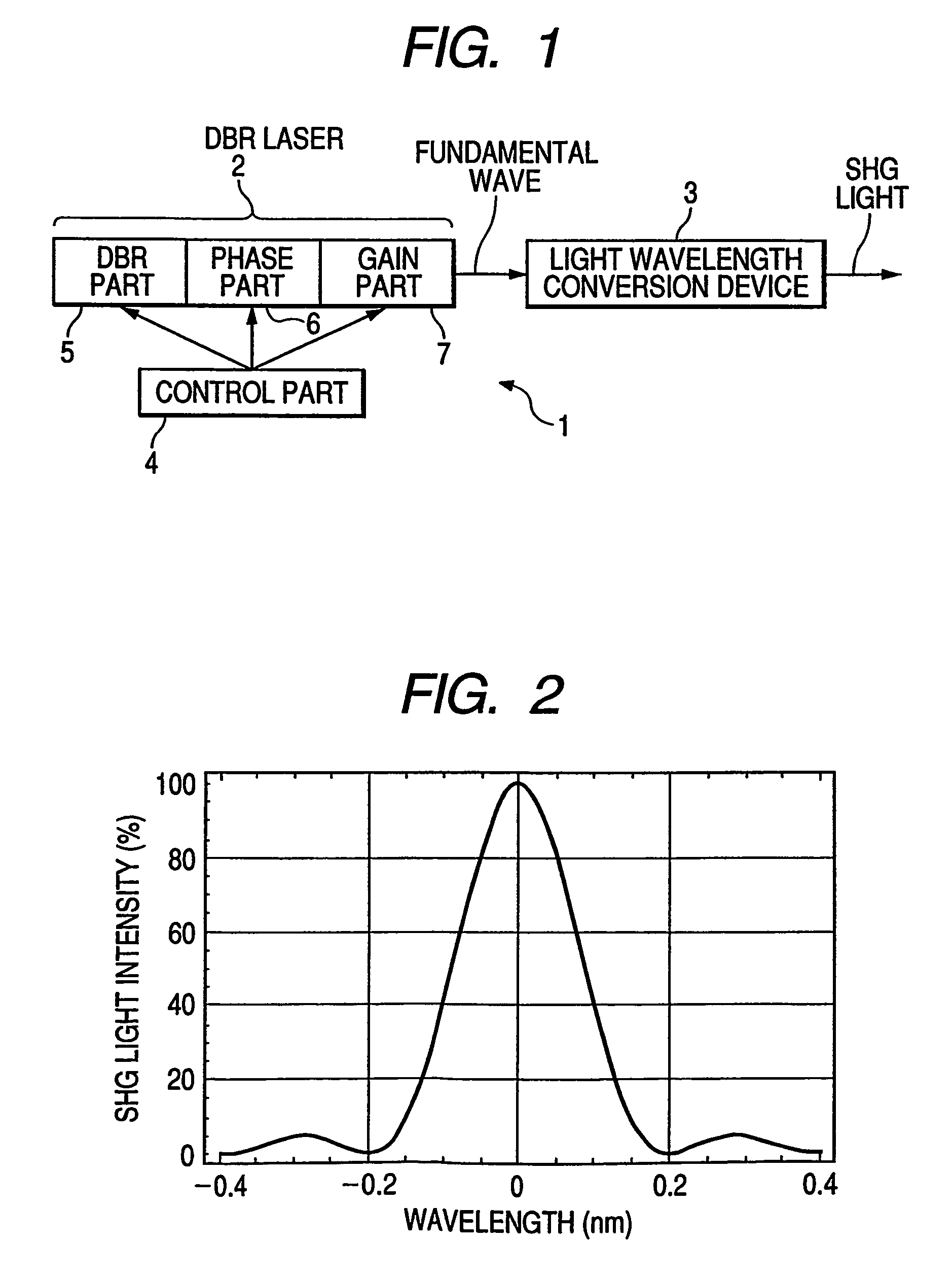
[0027]FIG. 1 is a structural diagram showing the modulation light source 1 according to this embodiment. In FIG. 1, the DBR laser 2 is composed of the DBR part 5 in which a diffraction grating is formed, the phase part 6, and the gain part 7, and generates fundamental light having a wavelength of 1,064 nm. The light wavelength conversion device 3 is made of LN crystal having a periodical polarization inversion waveguide structure, and subjects wavelength conversion to the fundamental light emitted from the DBR laser 2 to output an SHG light having a wavelength of 532 nm.

[0028]In this embodiment, the DBR part 5 is controlled for modulation using the current based on the PWM signal. The substantially constant current is supplied to the phase part 6 and the gain part 7 for a time period sufficiently longer than that corresponding to a maxi...

second embodiment

[0030]In the first embodiment, the example in which the PWM signal is inputted to only the DBR part 5 is described. Even when both the DBR part 5 and the phase part 6 are controlled for modulation using the current based on the PWM signal, the same effect can be obtained.

[0031]FIG. 5 shows a relationship among a current flowing through the DBR part 5, a current flowing through the phase part 6, and the oscillation wavelength of the fundamental wave. A contour line indicates a wavelength. The wavelength becomes smaller as a point is shifted from the origin to upper right. In this embodiment, for modulation control, the adjustment is performed in advance such that a point C in the drawing which is the phase matching wavelength of the light wavelength conversion device 3 becomes an ON value and a point D in the drawing becomes an OFF value.

[0032]In this embodiment, the modulation control is performed using the current based on the PWM signal in which a sum of the current flowing throug...

third embodiment

[0035]Next, a third embodiment of the present invention will be described with reference to the drawing.

[0036]FIG. 6 is a schematic structural view showing an image display apparatus according to a third embodiment of the present invention. In the drawing, reference numeral 701 denotes a green light source which is composed of a modulation light source and outputs green laser light as described in the first embodiment and the second embodiment, 703 denotes a red light source composed of a semiconductor laser module, 705 denotes a blue light source composed of a semiconductor laser module, 707 denotes a dichroic mirror, 709 denotes a horizontal scanning device, 711 denotes a vertical scanning device, and 713 denotes a projected surface.

[0037]Light beams outputted from the light sources 701, 703, and 705 are combined by the dichroic mirror 707. The combined light beam is scanned by the two scanning devices 709 and 711 to form a scanning line on the projected surface 713. When the ligh...


PUM

PropertyMeasurementUnit
wavelengthaaaaaaaaaa
phase matching wavelengthaaaaaaaaaa

Abstract

A modulation light source capable of maintaining thermal stability of a gain part is provided. A modulation light source includes a DBR laser having a DBR part, a phase part and a gain part, a light wavelength conversion device that receives a fundamental wave from the DBR laser and from which an SHG light is emitted, and a control means for controlling the DBR laser. A substantially constant current is supplied to the gain part for a modulation time period of a PWM signal. At least one of the DBR part and the phase part is controlled for modulation using a current based on the PWM signal.

Description

TECHNICAL FIELD[0001]The present invention relates to a modulation light source using a DBR (distributed Bragg reflector) laser, an image display apparatus including the same, and a light modulation method.BACKGROUND ART[0002]An SHG (second harmonic generation) laser light source has been proposed (see Japanese Patent Application Laid-Open No. 2002-043683). FIG. 8 shows its structure. As shown in this drawing, provided are a DBR laser 1010 which includes a DBR part 1013, a phase part 1012, and a gain part 1011, a SHG device 1020, and a control part 1030. The control part 1030 changes a current flowing through the DBR part 1013 and the phase part 1012 at a predetermined change current ratio to modulate an intensity of SHG light. The control part 1030 modulates the intensity of SHG light based on a result obtained by detection of a photo detector that receives second harmonic light from the SHG device 1020.[0003]A method of modulating a current flowing through the gain part 1011 based...

Claims


Application Information

Patent Timeline
Patent Type & Authority Patents(United States)
IPC IPC(8): H01S3/10H01S3/08G02F1/37H01S5/06H01S5/0625H01S5/068H01S5/125
CPCH01S5/06256H01S5/005H01S5/0092H01S5/0617H01S5/06253
Inventor FUJII, KAZUNARIFURUKAWA, YUKIO
Owner CANON KK
Why Eureka
Try Eureka