Video signal recording apparatus

a video signal and recording apparatus technology, applied in the field of dvd recorder and video signal recording apparatus, can solve the problems of troublesome users, unfinished recording, and inability to record video signals of portions exceeding 120 minutes, so as to prevent partial deterioration of picture quality of video signals recorded on optical disks, suppress complication of key operation during dubbing, and preserve the effect of video signal quality

Inactive Publication Date: 2008-08-26
FUNAI ELECTRIC CO LTD
View PDF14 Cites 5 Cited by
  • Summary
  • Abstract
  • Description
  • Claims
  • Application Information

AI Technical Summary

Benefits of technology

[0015]It is an object of the invention to provide a video signal recording apparatus which can record the entire video signal recorded on a digital videotape without generating any vacant area on an optical disk even when the substantial recoding time of a digital videotape is longer than a prescribed recording time, prevent partial deterioration in the picture quality of the video signal recorded on the optical disk and suppress complication of the key operation during dubbing.
[0030]Furthermore, since deterioration in the picture quality of the video signal recorded during a greater period which does not draw to the end of the recording is not generated, deterioration of the picture quality of the major part of the video signal recorded on the optical disk is prevented. Even when the deterioration occurs, the time generating the deterioration can be minimized.

Problems solved by technology

However, the first related art presents the following problem.
Thus, where the video signal reproduced from the digital videotape is recorded on the optical disk at the bit rate capable of recording the 120-minutes video signal without generating any vacant area, the video signal of the portion exceeding 120 minutes cannot be recorded on the optical disk.
Namely, assuming that the video signal is recorded to the end of the digital videotape in the long mode on the 80-minutes tape, where the video signal thus recorded on the digital videotape is recorded on the optical disk at the bit rate set corresponding to the long mode of the 80-minutes tape, the video signal recorded on the optical disk results in unfinished recording.
This is very troublesome for the user.
Thus, where only-once rewritable optical disk is employed, the capacity of this optical disk will be consumed unnecessarily.
Therefore, it is difficult to adopt this related art to solve the problem presented by the first related art, i.e., that a portion with the recording time exceeding 120-minutes of the video signal recorded on the digital videotape cannot be recorded on the optical disk.

Method used


Image

  • Video signal recording apparatus
  • Video signal recording apparatus
  • Video signal recording apparatus

Examples


embodiment 1

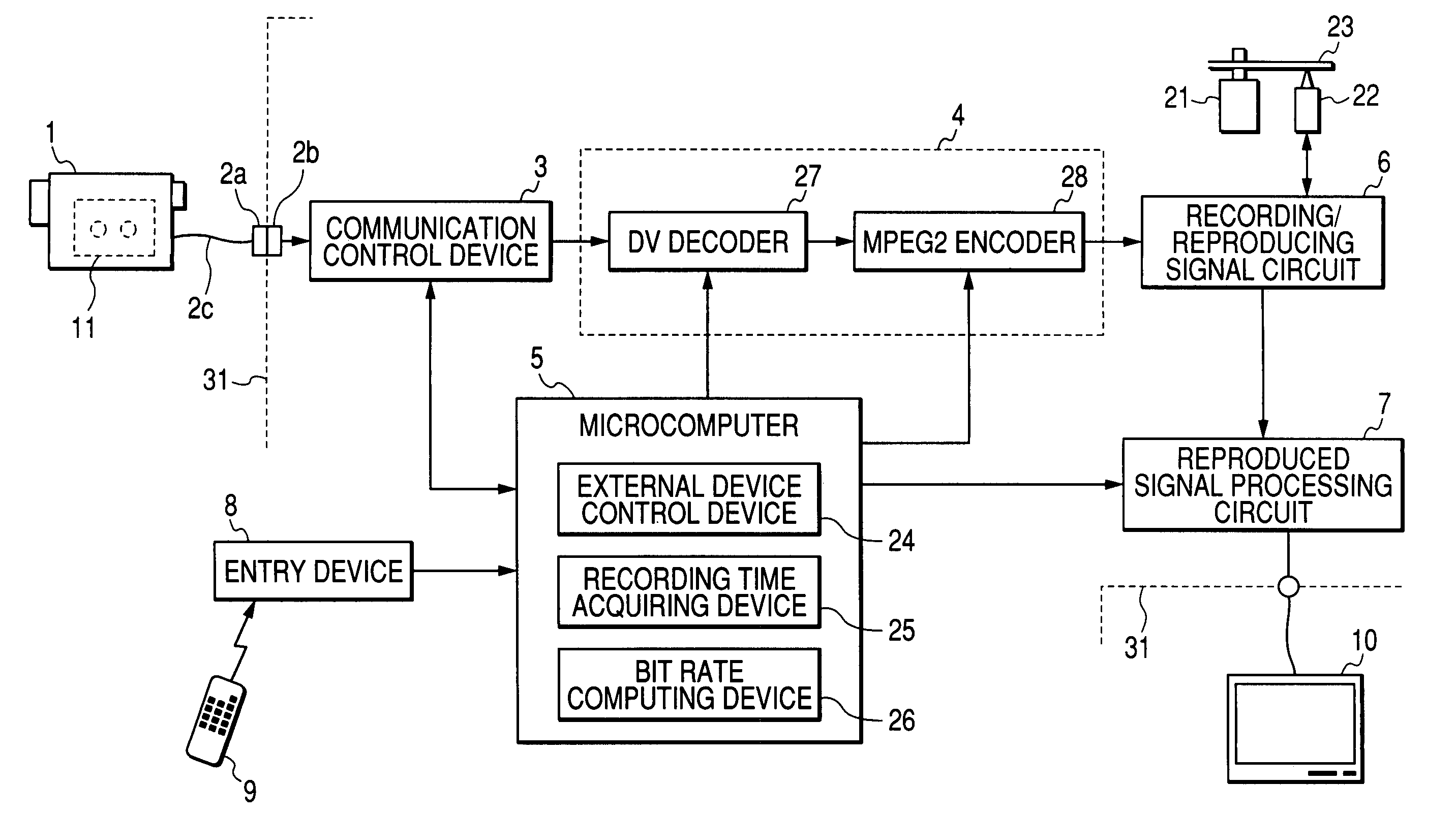
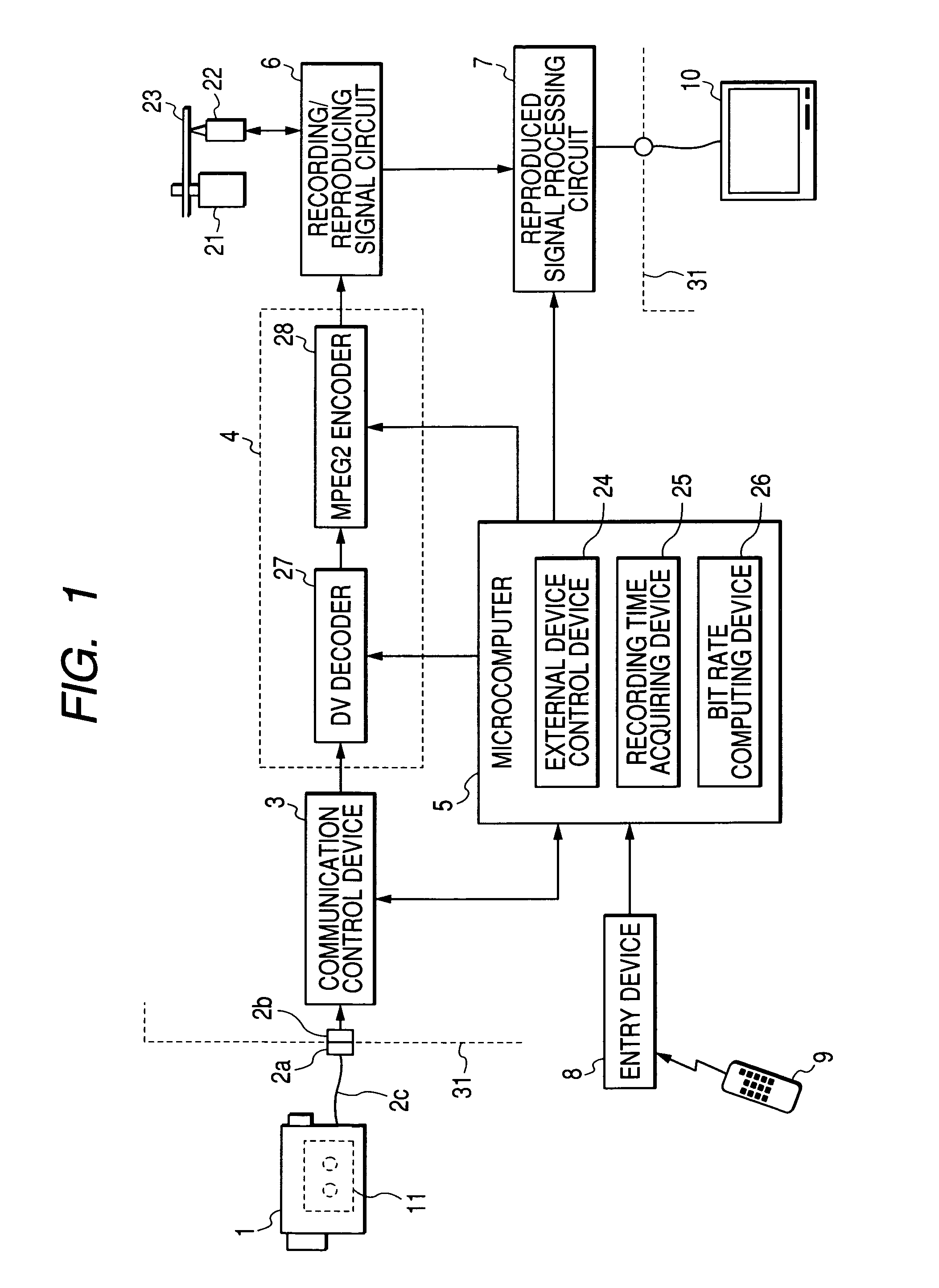
[0037]FIG. 1 is a block diagram showing the electronic configuration of a DVD recorder which is an embodiment of the video signal recording apparatus according to this invention.

[0038]In FIG. 1, a cable 2c and connectors 2a, 2b which connect a device body 31 of the DVD recorder to a digital video camera 1 are the cable and connectors standardized as IEEE 1394. The connector 2a is attached to the end of the cable 2c, and the connector 2b is attached to the device body 31 side of the DVD recorder.

[0039]A communication control device 3 exchanges information with the digital video camera 1 according to the communication method standardized as IEEE1394. The information (inclusive of information indicative of device type and information indicative of a list of acceptable commands) outputted from the digital video camera 1 during the information exchange is supplied to a microcomputer 5. Further, the information inclusive of the commands outputted from the microcomputer 5 is transferred to...

embodiment 2

[0073]The second embodiment will be explained below. The second embodiment has the same configuration as that in FIG. 1 as an electric configuration and is different from that in FIG. 1 only in the construction of the bit rate computing device 26. An explanation will be given of only the construction of the bit rate computing device 26.

[0074]In computing the bit rate when the video signal for recording which is the signal encoded by the encoder 28, the bit rate computing device 26 computes the bit rate so as to decrease when the recording draws to the end. Namely, the bit rate when the recording is started is set at a value (hereinafter referred to as a prescribed bit rate) which permits the video signal to be recorded on the optical disk 23 without generating any vacant area assuming that the recording time of the video signal is 120 minutes.

[0075]Assuming that the video signal corresponding to the recording time computed by the recording time acquiring device 25 has been recorded ...

embodiment 3

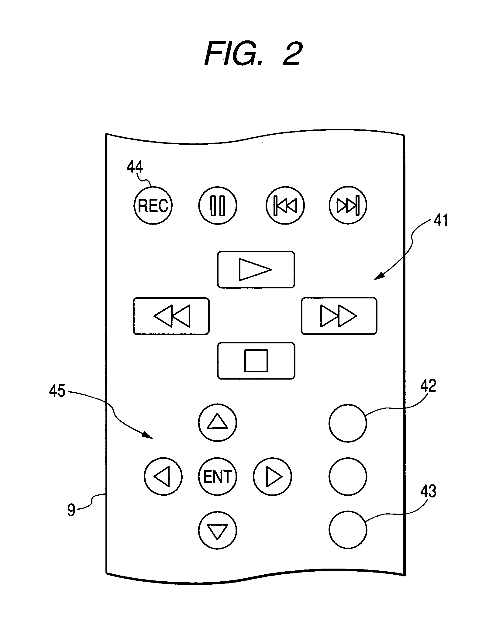
[0081]The third embodiment will be explained below. The third embodiment has the same configuration as that in FIG. 1 as an electric configuration and is different from that in FIG. 1 only in the arrangement of key switches on the remote controller 9 and the method of operating the key switches for the shift to the automated correction mode, thereby carrying out the recording on the optical disk 23. Therefore, an explanation will be given of only the arrangement of the key switches and the portion in the construction of the microcomputer 5 different from the first embodiment.

[0082]In the first embodiment, the key switch 43 on the remote controller 9 was employed as the automatic dubbing key. On the other hand, in the third embodiment, the automatic dubbing key is omitted so that the key switch 43 is employed as a key switch for entering the other instruction (allotted to the different key switch in the first embodiment). In the third embodiment, therefore, as compared with the first...


PUM

PropertyMeasurementUnit
recording timeaaaaaaaaaa
time acquiring deviceaaaaaaaaaa

Abstract

A recording time acquiring device is provided to acquire the recording time of the video signal recorded on the digital videotape on the basis of signals outputted from the digital video camera when the digital videotape is fast-forwarded from a leading position to an ending position of recording in the digital video camera. In an automated correction mode, a bit rate computing device records the video signal for recording on the optical disk on the basis of the recording time acquired by the recording time acquiring device.

Description

BACKGROUND OF THE INVENTION[0001]1. Field of the Invention[0002]The invention relates to a DVD recorder and a video signal recording apparatus for recording an encoded signal after a digital video signal outputted from a digital video camera for reproducing a digital videotape has been extended.[0003]2. Description of the Related Art[0004]In a digital video cassette tape, where a tape capable of recording a video signal for 80 minutes (hereinafter referred to as a 80-minutes tape) is employed, if a long mode is adopted, the video signal for 120 minutes can be recorded. For this reason, where the video signal recorded in the long mode on the 80-minutes tape is reproduced and a DVD-standard video signal converted from the video signal thus reproduced is recorded on an optical disk, for the purpose of minimizing deterioration of the video signal, the bit rate of the video signal when it is recorded on the optical disk was set at 5 Mbps which is the bit rate corresponding to the video s...

Claims


Application Information

Patent Timeline
Patent Type & Authority Patents(United States)
IPC IPC(8): H04N7/01H04N5/7826G11B20/10G11B27/031G11B27/032G11B27/034G11B27/34G11B27/36H04N5/00H04N5/76H04N5/765H04N5/77H04N5/775H04N5/782H04N5/85H04N5/91H04N5/92H04N5/926H04N9/79H04N9/804H04N21/4223H04N21/426H04N21/433H04N21/458H04N21/488
CPCG11B27/031H04N21/4882G11B27/034G11B27/34G11B27/36H04N5/765H04N21/4223H04N21/42646H04N21/4334H04N21/4583G11B27/032G11B2020/10833G11B2220/2562H04N5/772H04N5/775H04N5/85H04N9/7921H04N9/8042
Inventor YOSHIDA, SINJI
Owner FUNAI ELECTRIC CO LTD
Why Eureka
Try Eureka