Ion acceleration system for hadrontherapy

a technology of acceleration system and linac, which is applied in the field of ion acceleration system for hadrontherapy, can solve the problems of large installation surface, large installation surface, and large size of the center, and achieve the effects of reducing the cost of treatment, and improving the quality of linac output beam in dimension and divergen

Active Publication Date: 2008-09-09
ADVANCED ONCOTHERAPY PLC
View PDF2 Cites 21 Cited by
  • Summary
  • Abstract
  • Description
  • Claims
  • Application Information

AI Technical Summary

Benefits of technology

[0013]A further and important advantage of the invention is that it provides a system with a built-in accelerator where energy and current of the therapeutic beam can be varied easily and continuously in an active way. This last property is indeed also present in a synchrotron, although with higher complexity and error margins.
[0014]It is also underlined that commonly the quality of a Linac output beam is better in dimension and divergence compared with those of the synchrotrons and also of the cyclotrons. Since the emittances of the produced therapeutic beam are lower than those produced by the other accelerators, the mass and cost of the magnetic channels for beam transport, in particular for the rotating gantries used for the treatments, are reduced.
[0015]One more advantage should be recognized in the time structure of the therapeutic beam which is well suited to treatments using the technique of the “spot scanning”, as in use, for instance, at the PSI Center (Paul Scherrer Institute, CH-5232 Villigen, Switzerland).
[0016]The Linac, disclosed in the WO 2004 / 054331 and in U.S. Ser. No. 10 / 602,060 by the Requestor, can be used as the high frequency modular Linac, and its content is hereby included for reference.

Problems solved by technology

However, hadrontherapy centers equipped with a synchrotron are extremely complex as they require a high number of high technology equipments derived from the technology of particle accelerators.
In addition these centers are quite large, also due to the surface occupied by the synchrotron, and they require high investments and large installation surfaces that are not always available in the hospitals neighborhoods.

Method used


Image

  • Ion acceleration system for hadrontherapy
  • Ion acceleration system for hadrontherapy
  • Ion acceleration system for hadrontherapy

Examples


Embodiment Construction

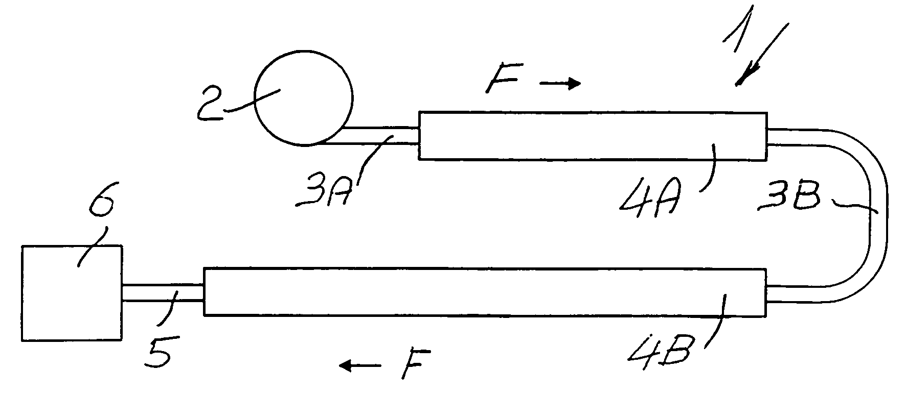
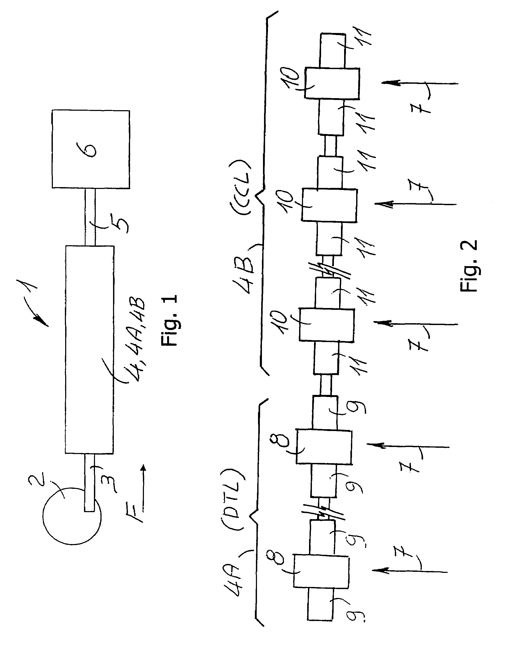
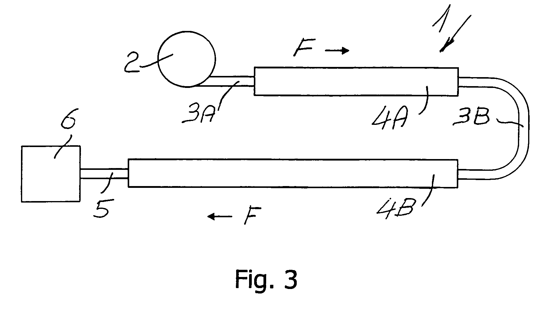
[0023]The components of the system according to the invention illustrated in FIGS. 1, 2 and 3 are the following:[0024]1 Ion acceleration system for hadrontherapy;[0025]2 Cyclotron;[0026]3 Medium Energy Beam Transfer line (MEBT);[0027]3A Medium-low Energy Beam Transfer line;[0028]3B Medium-high Energy Beam Transfer line;[0029]4 Modular Linac at high frequency, typically higher than 1 GHz;[0030]4A Modular Linac 4 DTL accelerating section whose number of modules depends on the application;[0031]4B Modular Linac 4 CCL accelerating section whose number of modules depends on the application;[0032]5 High Energy Beam Transport line (HEBT);[0033]6 Area for beam utilization;[0034]7 Power inputs;[0035]8 Modules of the accelerating section of the DTL structure;[0036]9 Single accelerating section of the DTL structure;[0037]10 Modules of the accelerating section of the CCL structure;[0038]11 Single accelerating section of the CCL structure;

[0039]F Beam direction.

[0040]As from FIG. 1, the ion acce...


PUM


Abstract

System for ion acceleration for medical purposes comprising a conventional or superconducting cyclotron, a radiofrequency linear accelerator (Linac), a Medium Energy Beam Transport line (MEBT) connected, at the low energy side, to the exit of the cyclotron, and at the other side, to the entrance of the linear radiofrequency accelerator, as well as a High Energy Beam Transport line (HEBT) connected at high energy side to the radiofrequency linear accelerator exit and at the other end, to a system for the dose distribution to the patient.The high frequency of operation of the Linac allows for a reduced consumption and a remarkable compactness facilitating its installation in hospital structures. The use of a modular LINAC allows varying in active way the energy and the current of the therapeutic beam, having a small emittance and a time structure adapted to the dose distribution based on the technique known as the “spot scanning”.

Description

FIELD OF THE INVENTION[0001]The present invention relates to a ion acceleration system for hadronthrapy according to the preamble of claim 1, and more precisely to a beam acceleration system for either nuclei (e.g. 12C6+) or molecules (e.g. H+2) with a mass number higher than 1, henceforth named “ions”, for example for medical use in hadrontherapy.BACKGROUND OF THE INVENTION[0002]As known, hadrontherapy is the therapeutic technique that uses beams either of protons or heavier charged particles with mass number higher than 1.[0003]It is equally known that in protontherapy, that is that particular hadrontherapy technique based on the use of proton beams, therapeutic beams of relatively low current (of the order of some nanoamperes) are used, with energies in the range 60 to 250 MeV, and a velocity interval between about 25% and 62% of the velocity of light.[0004]It is also observed that in the case of different ions, therapeutic beams with lower currents and higher energies are requir...

Claims


Application Information

Patent Timeline
Patent Type & Authority Patents(United States)
IPC IPC(8): A61N5/00
CPCG21K5/04H05H13/00H05H9/04
Inventor AMALDI, UGOCRESCENTI, MASSIMOZENNARO, RICCARDO
Owner ADVANCED ONCOTHERAPY PLC
Why Eureka
Try Eureka