Split outer tube anti-walkout bushing

a technology of outer tubes and bushings, which is applied in the direction of shock absorbers, machine supports, transportation and packaging, etc., can solve the problems of cross section distortion, and variations in the diameter of spring ends, so as to avoid high point load stress, reduce cost, and reduce cost

Inactive Publication Date: 2008-11-18
THE PULLMAN CO
View PDF7 Cites 7 Cited by
  • Summary
  • Abstract
  • Description
  • Claims
  • Application Information

AI Technical Summary

Benefits of technology

[0008]The present invention provides the art with a pivot bushing which provides the improved performance of the double-ended crimped bushings while still allowing for the use of the lower cost drawn shell outer metal. The present invention includes a split outer metal having one end crimped toward the inner metal with the other end forming a radially outwardly extending flange. A separate stamping can be attached to the flanged end in order to provide the compression and restriction for the elastomer. The outer metal of the present invention can be manufactured from the lower cost drawn shell material and because of its split configuration which is oriented towards the scarf gap of the spring, high point load stresses are avoided because the split outer metal design allows for very small radial deflections of the outer metal.

Problems solved by technology

While these elastomer isolated pivot bushings have performed satisfactorily in the field, they are not without their problems.
The various problems associated with these prior art pivot bushings include variations in the diameters of the spring ends and distortion of the cross section in the area where the pivot bushing is pressed into the spring ends.
Also, in the higher load applications, it is not uncommon for the outer metal to split due to high loads.
Thus, with curled end bushings, the heat treatment of the entire bushing is not a possibility.
While this DOM tubing will increase the strength of the tubing, it also significantly increases the manufacturing costs associated with the pivot bushing.

Method used


Image

  • Split outer tube anti-walkout bushing
  • Split outer tube anti-walkout bushing
  • Split outer tube anti-walkout bushing

Examples


Embodiment Construction

[0019]The following description of the preferred embodiment(s) is merely exemplary in nature and is in no way intended to limit the invention, its application, or uses.

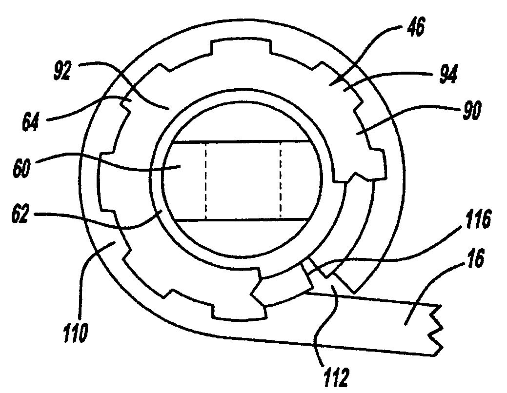
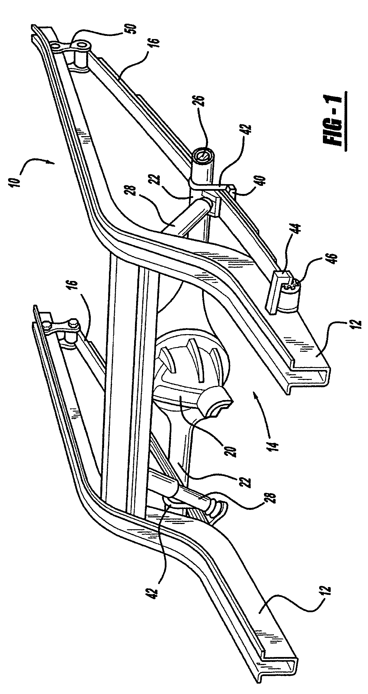
[0020]Referring now to the drawings in which like reference numerals designate like or corresponding parts throughout the several views, there is shown in FIG. 1 a truck or bus rear suspension incorporating the unique bushing in accordance with the present invention and which is designated generally by the reference numeral 10. Rear suspension 10 comprises a frame 12, a drive axle 14 and a pair of springs 16. Frame 12 supports a body (not shown) and other components of the vehicle which are generally identified as the “sprung mass”. Drive axle 14 includes a differential 20 which receives torque from an engine (not shown) through a rotating propeller shaft (not shown). Drive axle 14 also includes a pair of hollow tubes 22 that each extend out to a respective wheel assembly (not shown). Disposed within each of tubes 22 ...


PUM


Abstract

A pivot bushing for a suspension system has an inner metal and a split outer metal with an elastomeric bushing disposed between the metals. The split outer metal has one end which is partially closed by an inwardly curved portion and one end which is open. The assembly of the bushing is through the open end. Once assembled the open end is closed by placing a cover over the open end and crimping the cover to a flange formed at the open end. In another embodiment, the cover is inserted into the outer metal and the split outer metal is crimped to secure the cover in place.

Description

CROSS-REFERENCE TO RELATED APPLICATIONS[0001]This application claims the benefit of U.S. Provisional Application No. 60 / 655,752, filed on Feb. 24, 2005. The disclosure of the above application is incorporated herein by reference.FIELD OF THE INVENTION[0002]The present invention is related to a device which secures a spring to a vehicle for use in suspension systems for trucks, buses and the like. More particularly, the present invention is related to an improved bushing design which interfaces between a leaf spring and the attachment point on the frame for the leaf spring.BACKGROUND OF THE INVENTION[0003]Truck and bus suspensions are commonly designed using a pair of leaf springs between both the front and rear axles of the vehicle (the unsprung portion) and the body of the vehicle (the sprung portion). The leaf springs are normally a plurality of arcuately shaped steel or composite leafs that are stacked together to form the leaf spring. The axle of the vehicle is normally secured ...

Claims


Application Information

Patent Timeline
Patent Type & Authority Patents(United States)
IPC IPC(8): F16F7/00
CPCB60G11/12F16F1/3863B60G2200/31B60G2202/112
Inventor MCLAUGHLIN, RONALD J.RAYMOND, JEFF
Owner THE PULLMAN CO
Why Eureka
Try Eureka