Supercharge Your Innovation With Domain-Expert AI Agents!

Positive crankcase ventilation device and system

a technology of positive crankcase and ventilation device, which is applied in the direction of charge feed system, non-fuel substance addition to fuel, combustion engine, etc., can solve the problems and achieve the effect of saving component cost and assembly tim

Inactive Publication Date: 2009-04-07
GM GLOBAL TECH OPERATIONS LLC
View PDF17 Cites 2 Cited by
  • Summary
  • Abstract
  • Description
  • Claims
  • Application Information

AI Technical Summary

Benefits of technology

[0004]In one embodiment, the structural member is in the cam cover which operatively connects to the crankcase. The internal flow passage may be machined, fitted, cast or molded in the cam cover. In one embodiment, the internal flow passage, cam cover and a tubular fitting configured for attachment with a passage member such as PCV tubing are formed from the same base material as a single component, thus potentially saving component cost and assembly time. In another embodiment, the structural member is a separate component that is rigidly secured within an opening of the cam cover. For example, the structural member may be a substantially annular disk which is press-fit in a cylindrical bore in the cam cover.

Problems solved by technology

In one embodiment, the internal flow passage, cam cover and a tubular fitting configured for attachment with a passage member such as PCV tubing are formed from the same base material as a single component, thus potentially saving component cost and assembly time.

Method used


Image

  • Positive crankcase ventilation device and system
  • Positive crankcase ventilation device and system
  • Positive crankcase ventilation device and system

Examples


Embodiment Construction

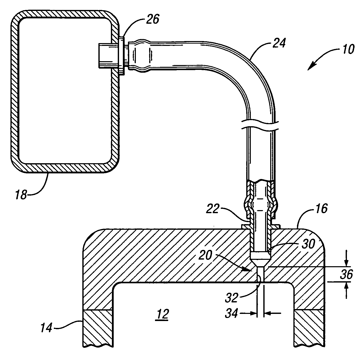
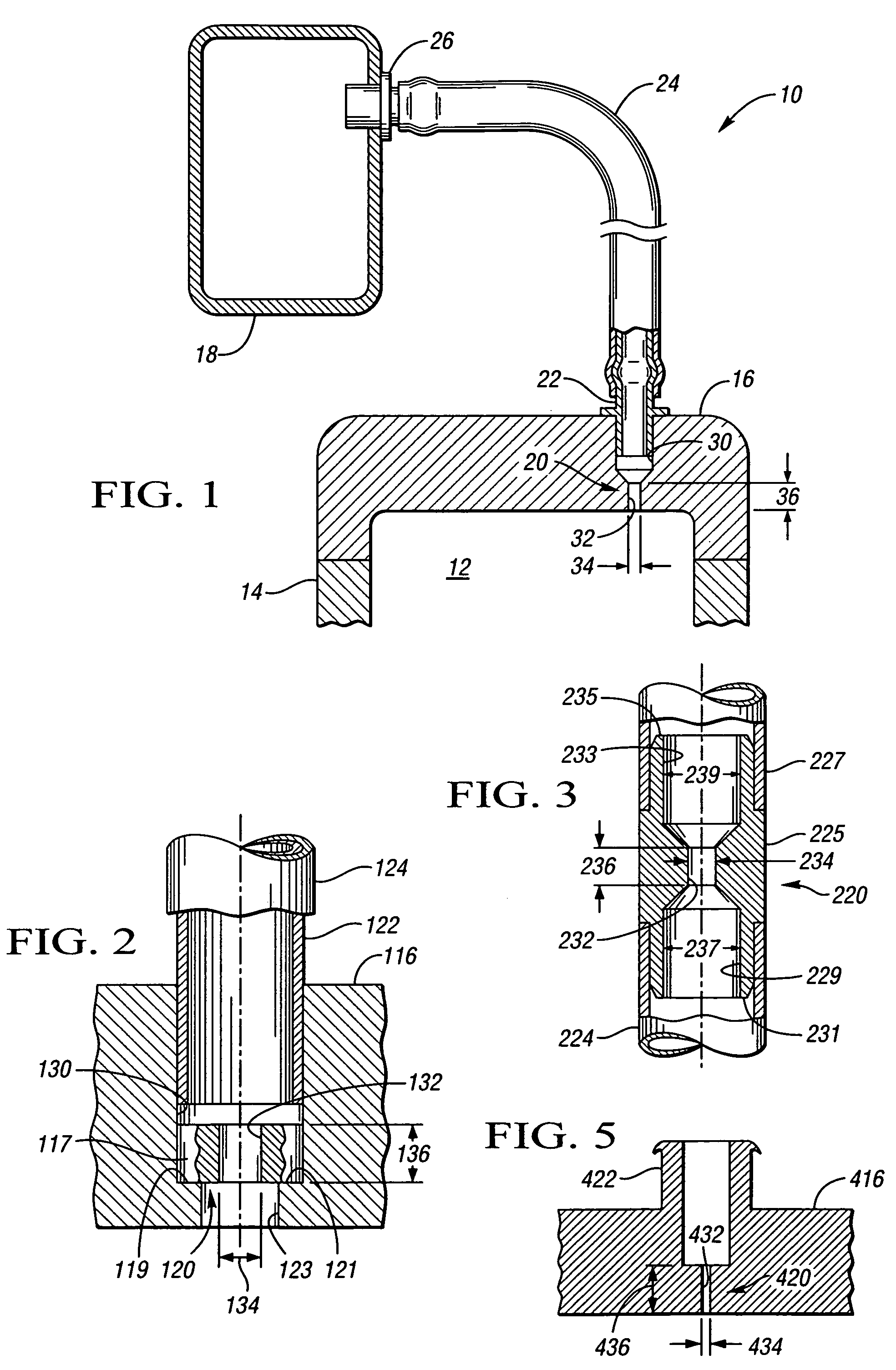
[0012]Referring to the drawings, wherein like reference numbers refer to like components, a PCV system 10 is shown in FIG. 1. The PCV system 10 allows recirculation of crankcase vapors and blow-by gasses emanating from engine cylinders, not shown but housed within the cam interior space 12 that is enclosed by a crankcase 14 and a cylinder head cam cover 16. The engine cylinders are contained within the crankcase 14 below the cam cover 16. The PCV system 10 routes the crankcase vapors from the interior space 12 to an air intake portion 18. The air intake portion 18 may be an intake manifold or an intake passage to the cylinders of the engine, as is understood by those skilled in the art.

[0013]The PCV system 10 includes a PCV device 20 which is operatively connected with a tubular fitting 22 mounted on the cam cover 16. The PCV system 10 also includes a passage member 24, also referred to as a PCV tube, which connects between fitting 22 and a second fitting 26 mounted on the air intak...


PUM


Abstract

A PCV device for recirculation of crankcase air has a structural member with a tubular, substantially linear internal flow passage characterized by a length and diameter with a ratio of length to diameter that attenuates noise and acts as a restrictive orifice to at least partially control flow volume therethrough. A PCV system for an engine includes a structural member as described above placed in fluid communication with a passage member to partially form a flow path between an interior portion of an engine crankcase and an air intake portion of the engine. The flow path has an absence of any flow restriction with a diameter smaller than the diameter of the structural member.

Description

TECHNICAL FIELD[0001]This invention relates to a positive crankcase ventilation system and, more particularly, a positive crankcase device with improved noise attenuation.BACKGROUND OF THE INVENTION[0002]It is known in the art to provide positive crankcase ventilation (PCV) systems for internal combustion engines to reduce emission of contaminants by drawing crankcase vapors from the engine crankcase into the engine cylinders for burning. This is typically done by venting the vapors through a cylinder head cam cover attached to the crankcase to an intake air passage, such as an intake manifold, via a passage member such as a PCV tube. A typical PCV system may include a PCV control valve or orifice mounted in the flow path between the crankcase and the air intake portion. During engine operation, a vacuum is developed in the manifold which draws crankcase vapors through the PCV system into the manifold where it mixes with intake air to be delivered to the engine cylinders. In designi...

Claims


Application Information

Patent Timeline
Patent Type & Authority Patents(United States)
IPC IPC(8): F02B25/06
CPCF01M13/023F02M25/06F02M35/10222F01M13/0405Y02T10/121Y02T10/12
Inventor HAZELTON, GARY J.GRIFFITHS, LEONARD BARRY
Owner GM GLOBAL TECH OPERATIONS LLC
Features
  • R&D
  • Intellectual Property
  • Life Sciences
  • Materials
  • Tech Scout
  • Unparalleled Data Quality
  • Higher Quality Content
  • 60% Fewer Hallucinations
Learn More