Integrated circuit current reference

a current reference and integrated circuit technology, applied in the direction of electric variable regulation, process and machine control, instruments, etc., can solve the problems of inability to provide thin film resistors, inability to accurately detect the initial accuracy, and inability to accept large temperature errors, etc., to achieve high quality, highly accurate and stable reference current, and high reference current high accuracy

Active Publication Date: 2009-07-07
ANALOG DEVICES INC
View PDF5 Cites 19 Cited by
  • Summary
  • Abstract
  • Description
  • Claims
  • Application Information

AI Technical Summary

Benefits of technology

This approach enables the generation of a highly accurate and stable reference current without increasing the pin count or external components, reducing the need for costly trimming and improving temperature stability, thus enabling cost-effective and accurate IC operations even with low-quality internal resistors.

Problems solved by technology

However, for some low cost IC processes, thin film resistors are not available, and other types such as polysilicon or diffused resistors must be used.
In these cases, initial accuracy may be no better than 30% or more and TCs can be on the order of 1000 ppm / ° C. or larger, leading to unacceptably large errors over temperature.
Expensive laser or fuse-blow trimming can improve initial accuracy, but have little to no effect on the internal resistor's non-ideal temperature and voltage characteristics.
Extreme cost pressures on some ICs push manufacturers to use inexpensive IC processes and lower pin count packaging.
But as noted above, these inexpensive processes typically lack high quality resistors, so that an internally generated reference current may be unacceptably inaccurate.
And a limited pin count may make an application of a high quality current reference for internal bias generation or current limit detection impractical.

Method used


Image

  • Integrated circuit current reference
  • Integrated circuit current reference
  • Integrated circuit current reference

Examples


Embodiment Construction

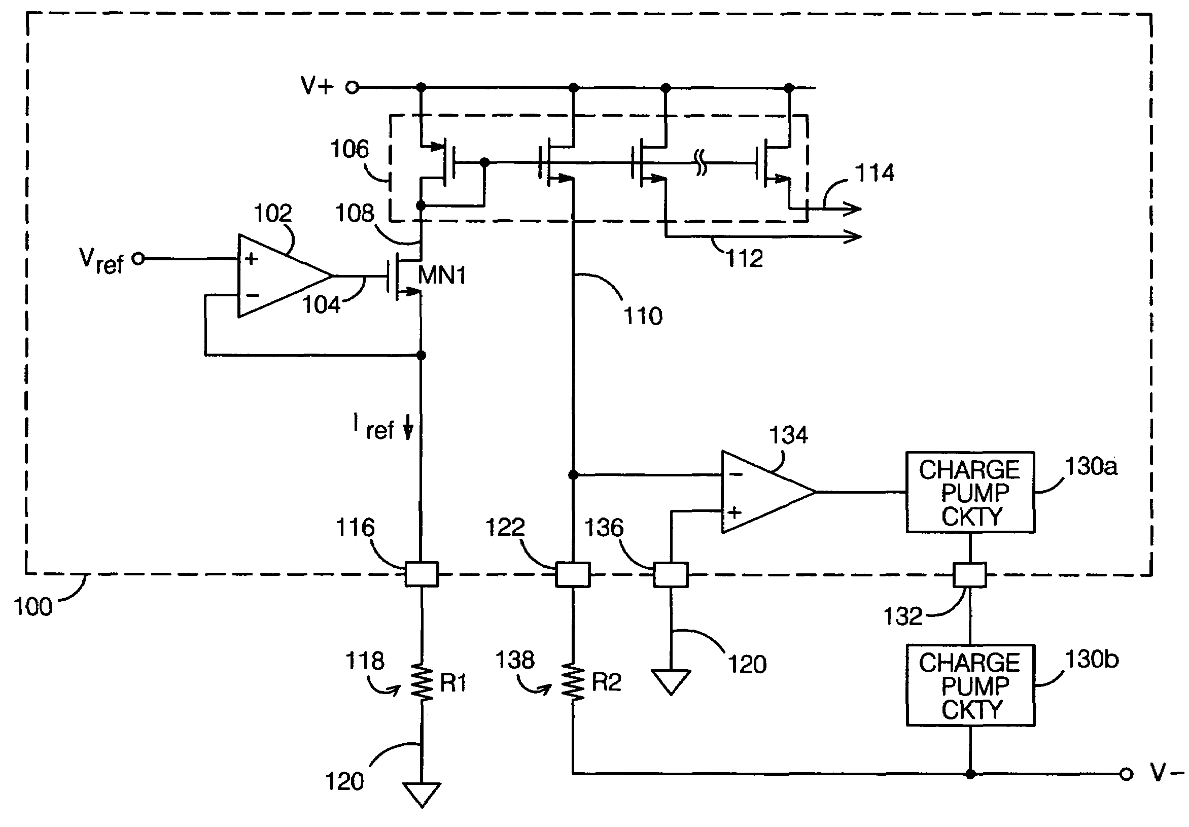
[0018]One possible embodiment of an IC current reference in accordance with the present invention is shown in FIG. 2. An IC 100 receives a reference voltage Vref from a voltage source (not shown). Vref is preferably buffered with an amplifier 102, and the buffered output 104 is used to drive a transistor MN1, shown here as an NMOS FET, though other transistor types could also be used. The IC also contains a current mirror 106 referred to a positive supply voltage V+, which has an input 108 and at least one output (110, 112, 114). The transistor's current circuit is connected between the current mirror and one of the IC's I / O pins 116; in this example, MN1's drain is connected to current mirror input 108 and its source is connected to I / O pin 116.

[0019]To generate a reference current, an external resistor 118 is connected between I / O pin 116 and a fixed voltage, typically circuit common (120). Resistor 118 has a resistance R1. In operation, Vref drives FET MN1 to conduct a current Ir...


PUM


Abstract

An IC current reference includes a reference voltage Vref, a current mirror, and a transistor connected between the mirror input and a first I / O pin and which is driven by Vref. A resistor external to the IC and having a resistance R1 is coupled to the first I / O pin such that it conducts a current Iref which is proportional to Vref / R1; use of a low TC / VC resistor enables Iref to be an accurate and stable reference current. The current mirror provides currents which are proportional to Iref, at least one of which is provided at a second I / O pin for use external to the IC. One primary application of the reference current is as part of a regulation circuit for a negative supply voltage channel, which can be implemented with the same number of external components and I / O pins as previous designs, while providing superior performance.

Description

BACKGROUND OF THE INVENTION [0001]1. Field of the Invention[0002]This invention relates generally to integrated circuit (IC) current references, and more particularly, to IC current references which provide reference currents for use both internal and external to an IC.[0003]2. Description of the Related Art[0004]Integrated circuits (ICs) often require the use of a reference current. Such currents are used, for example, as a reference for a current limit detection circuit, to generate bias currents, or for any of a number of other purposes.[0005]A reference current is typically generated by applying a reference voltage generated internally to the IC across the terminals of an internal resistor. Such an arrangement is illustrated in FIG. 1. Here, an IC 10 receives a reference voltage Vref from a voltage source (not shown). Vref is buffered with an amplifier 12, and the buffered output 14 is used to drive a transistor 16, shown here as an NMOS FET, though other transistor types could ...

Claims


Application Information

Patent Timeline
Patent Type & AuthorityPatents(United States)
IPC IPC(8): G05F3/16G05F1/10
CPCG05F3/262
InventorBARROW, JEFFREY G.
OwnerANALOG DEVICES INC