Luminous display device

a technology of luminous display and display image, which is applied in the direction of shaving accessories, lighting and heating devices, instruments, etc., can solve the problems of insufficient light of display image and generation of non-uniform brightness of virtual image of display image, and achieve the effect of efficient focus

Active Publication Date: 2009-10-06
YAZAKI CORP
View PDF11 Cites 86 Cited by
  • Summary
  • Abstract
  • Description
  • Claims
  • Application Information

AI Technical Summary

Benefits of technology

[0013]It is therefore an objective of the present invention to solve the above problem and to provide a luminous display device, by which the illumination light from the backlight can be efficiently used and the virtual image of the display image displayed on the liquid crystal display can be subjected to be seen to the driver on the reflecting members with a sufficient and uniform brightness even if the liquid crystal display is arranged with an inclination to the line of sight reflected by the reflecting members and therefore the liquid crystal display is not arranged in parallel with the reflecting members.
[0020]With the construction described above, the illumination light from the backlight can be used efficiently. A gap of an optical path from the backlight to the eye point between the upper side and the lower side of the display image can be prevented from occurring and therefore, a virtual image of the displayed image being seen from the eye point can be prevented from having nonuniformity in brightness.
[0022]With the construction described above, in comparison with a case in which the focusing lens member is constructed with a single focusing lens, a curvature of a convex surface of the lens can be small. Therefore, the making of the lens can be easy and a thickness of the focusing lens member in a direction of the line of sight can be small.
[0024]With the construction described above, by making each focusing lens focus the beams of the illumination light from the corresponding point light source, the light beams of the whole illumination light can be efficiently focused into a desired range.

Problems solved by technology

Such a deviation makes a part of the light of an image run off to the outside of the reflecting members, causing an insufficient amount of light of the display image.
However, if the liquid crystal display and the backlight are arranged in such a manner as described above, a gap of the optical path from the backlight to the driver between the upper side and the lower side of the display image is generated, so that a difference takes place in a degree of attenuation in the light of an image, causing generation of nonuniformity in brightness for the virtual image of the display image, which is seen by the driver.

Method used


Image

  • Luminous display device
  • Luminous display device
  • Luminous display device

Examples


Embodiment Construction

[0038]In the following, the preferred embodiments of a luminous display device according to the present invention will be explained with reference to the attached drawings.

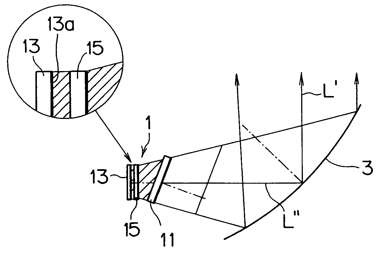
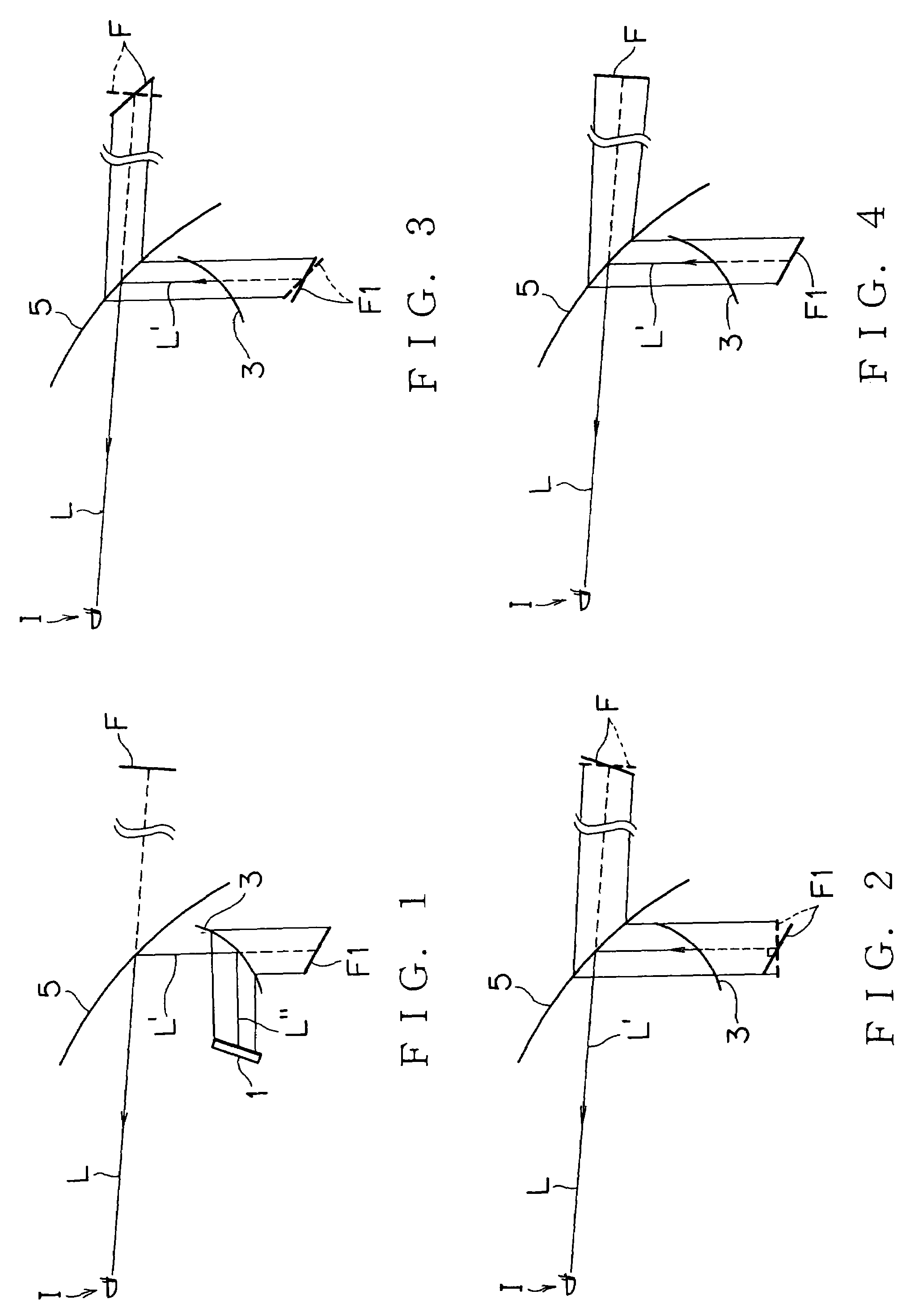
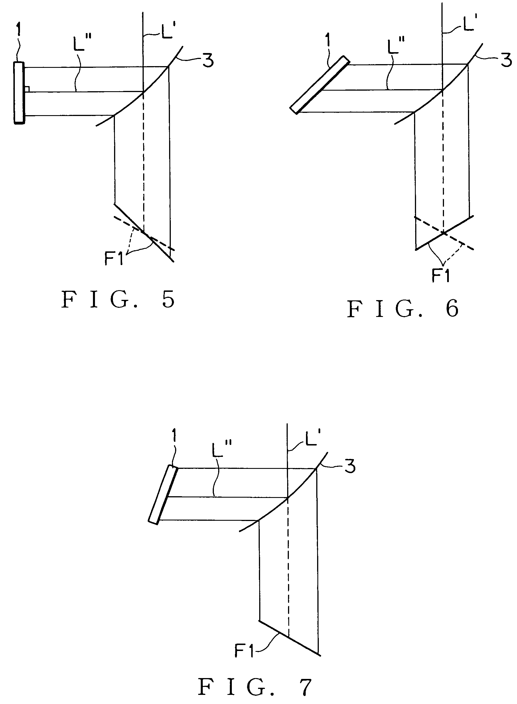
[0039]FIG. 1 shows an outline of a construction of a luminous display device according to a preferred embodiment of the present invention. The luminous display device according to the preferred embodiment is applied to a head-up display, in which light of a display image from a luminous display unit 1 received in a dash-board (not shown in the figure) of a vehicle is reflected and enlarged by a concave mirror 3 (i.e. reflecting member), reached to an eye point I of a driver via reflection by a windshield 5, and seen by the driver with superposing a virtual image F of the display image on a view in front of the windshield.

[0040]In detail, the driver sees a virtual image of a first virtual image F1 located in the rear of the concave mirror 3 as a final virtual image F of the display image located in front of the win...


PUM

PropertyMeasurementUnit
optical axisaaaaaaaaaa
focal distanceaaaaaaaaaa
brightnessaaaaaaaaaa

Abstract

In the rear of a liquid crystal display arranged with an inclination to a line of sight reflected by a concave mirror, a backlight and a focusing lens member are arranged in such a manner that the backlight and the focusing lens member are positioned on a plane perpendicular to the line of sight reflected by the concave mirror, and the focusing lens member focuses beams of illumination light from the backlight in such a manner that the beams of illumination light stays within a range of the liquid crystal display.

Description

BACKGROUND OF THE INVENTION[0001](1) Field of the Invention[0002]The present invention relates to a luminous display device which reflects light of a display image emitted from a liquid crystal display by means of transmission of illumination light from a backlight so as to provide the reflected light to be seen.[0003](2) Description of the Related Art[0004]So far, for example in a vehicle, in order to make a driver see various information by superposing on a view in front of a windshield, a head-up display has been used, in which light of a display image from a liquid crystal display in a dash-board is reflected to the side of the driver by the windshield or a combiner arranged on this side of the windshield, so that a virtual image of the display image can be seen on the windshield or the combiner.[0005]Further, in a vehicle, in some cases, in order to lighten the burden imposed on driver's eyes due to a large change in a focal distance during eye motion upon traveling of the vehi...

Claims


Application Information

Patent Timeline
Patent Type & Authority Patents(United States)
IPC IPC(8): G02F1/1335
CPCG02B27/0101G02B2027/0118G02B2027/011
Inventor NAKAMURA, GOSUGIYAMA, TETSUYA
Owner YAZAKI CORP
Why Eureka
Try Eureka