Power generation system

a power generation system and power generation technology, applied in the direction of instruments, process and machine control, material dimension control, etc., can solve the problems of not being able to maintain dynamic power balance between sources and decrease power demand, so as to reduce power demand, maintain power balance, and reduce load

Inactive Publication Date: 2010-03-16
GENERAL ELECTRIC CO
View PDF11 Cites 23 Cited by
  • Summary
  • Abstract
  • Description
  • Claims
  • Application Information

AI Technical Summary

Benefits of technology

[0008]If a power or energy source is power or rate limited in an isolated system with low inertia, it may not be possible to maintain dynamic power balance between source and load during system disturbances unless the demands of the load can be reduced. Fortunately many system loads have a natural tendency to decrease power demand as a function of voltage, frequency, or both. Therefore, by allowing the system frequency, voltage, or both to transiently droop, power balance can be maintained. In some cases this will allow the available generation to be used to its maximum potential, resulting in minimal equipment cost consistent with the power quality requirements of the application.

Problems solved by technology

If a power or energy source is power or rate limited in an isolated system with low inertia, it may not be possible to maintain dynamic power balance between source and load during system disturbances unless the demands of the load can be reduced.
Fortunately many system loads have a natural tendency to decrease power demand as a function of voltage, frequency, or both.

Method used


Image

  • Power generation system
  • Power generation system
  • Power generation system

Examples


Embodiment Construction

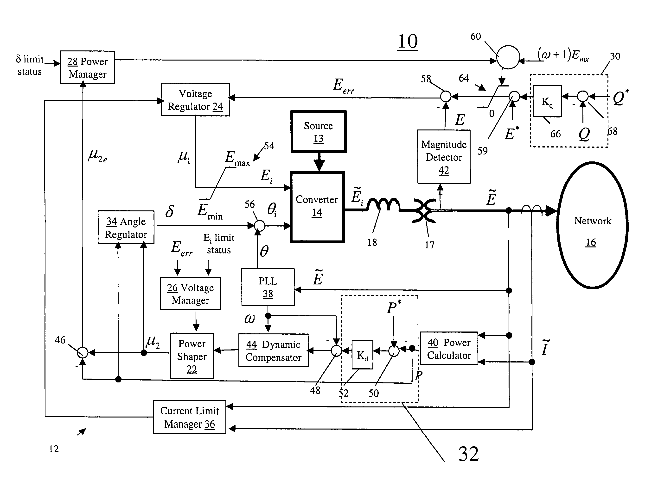
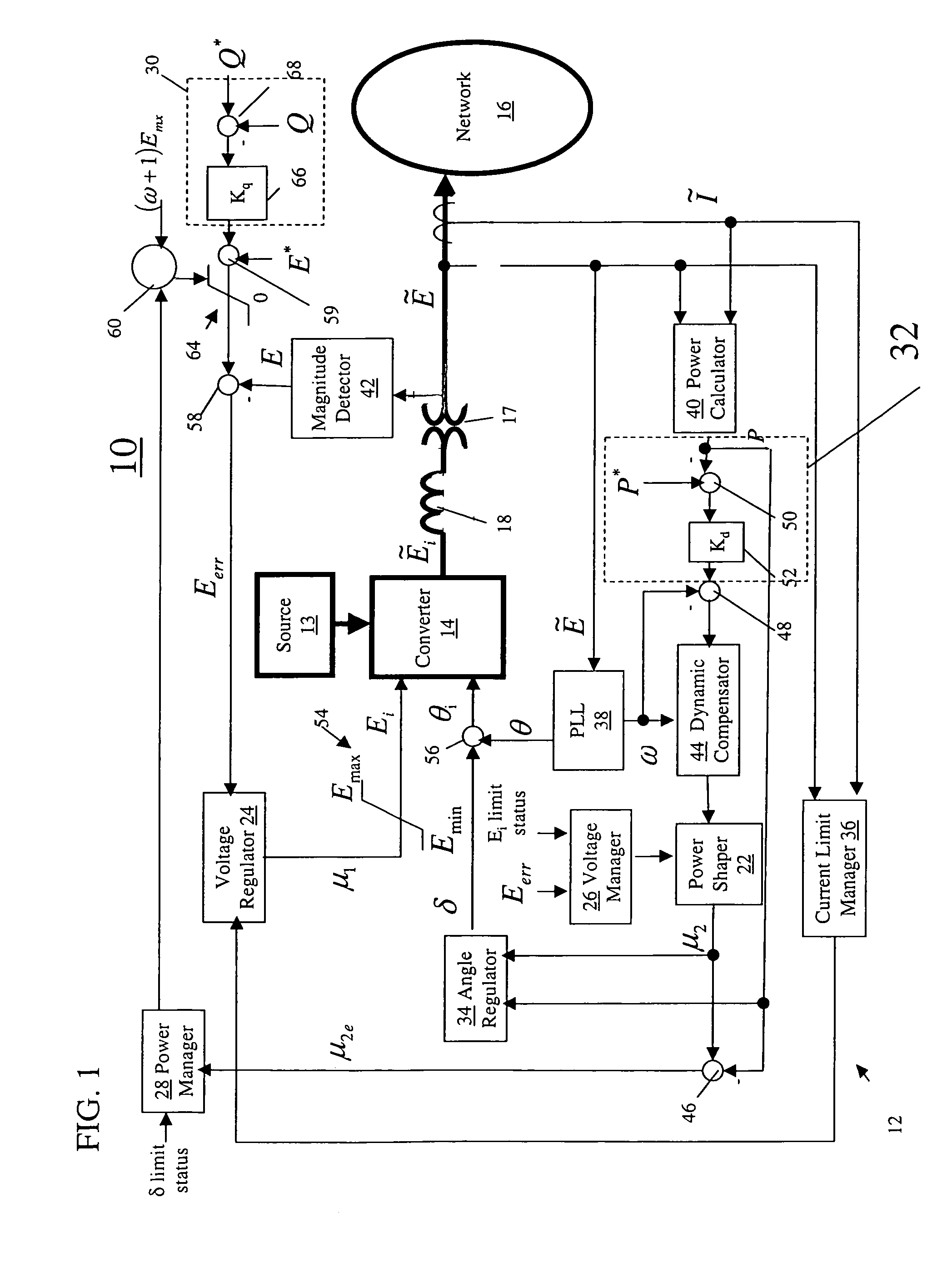
[0018]FIG. 1 is a block diagram of a power generation system in accordance with one embodiment wherein a power generation system 10 comprises a converter 14 configured for supplying power from a constrained power or energy source 13 to a power network 16, and a control system 12 configured for balancing instantaneously available power from the constrained source against demanded load from the power network by dynamically adjusting power network voltage, power network frequency, or a combination of power network voltage and power network frequency. The power connections are shown simply with single lines, but typically three phase power is used. As used herein, “instantaneously available power” means the maximum power available at any instant of time, and “constrained source” means a power or energy source that is inherently limited in dynamic response and power magnitude (that is, not always able to supply the instantaneous power requirements of the network).

[0019]Converter 14 may c...


PUM


Abstract

A power generation system includes a converter configured for supplying power from a constrained power or energy source to a power network and a control system configured for balancing instantaneously available power from the constrained source against demanded load from the power network by dynamically adjusting power network voltage, power network frequency, or a combination of power network voltage and power network frequency.

Description

BACKGROUND[0001]The invention relates generally to power generation systems and more particularly to systems configured for supplying power from constrained power or energy sources.[0002]Small and medium size generators are increasingly being considered for use in distribution networks because of the changing regulatory and market environment and because of the potential for energy savings and service improvements which may result from such use. A strong interest also exists in distributed generator (DG) systems that provide backup power capability and grid independent operation.[0003]Grid independent operation occurs when a system of generators operates independently of the bulk power system to deliver power to loads at nominal voltage and frequency within an acceptable tolerance band. Grid independent operation can be extremely challenging for DG systems supplying dynamic loads such as motors, especially when non-conventional generators such as fuel cells, wind turbines, micro-tur...

Claims


Application Information

Patent Timeline
Patent Type & Authority Patents(United States)
IPC IPC(8): G05D11/00
CPCH02J3/06
Inventor DELMERICO, ROBERT WILLIAMACHILLES, ALFREDO SEBASTIAN
Owner GENERAL ELECTRIC CO
Why Eureka
Try Eureka