Intervertebral implant

a technology of intervertebral implants and implants, which is applied in the field of intervertebral implants, can solve the problems of not being secured against axial displacement, and achieve the effects of facilitating fusion assessment, and optimal adaptation of apposition surfaces

Active Publication Date: 2010-04-06
SYNTHES USA
View PDF22 Cites 183 Cited by
  • Summary
  • Abstract
  • Description
  • Claims
  • Application Information

AI Technical Summary

Benefits of technology

[0006]The advantages achieved according to the invention include simple handling, since introduction of the implant proceeds very quickly because of the distractibility of the implant and a simple set of instruments. In this way, safety is increased, and the time required for the implantation is reduced. The distance between the two apposition parts can be changed by rotating the threaded spindle on the inside thread, in stepless manner.
[0024]In yet another embodiment, the intervertebral implant is produced at least partially from a material permeable for X-rays, preferably from PEEK. This makes it possible to achieve the advantage that the fusion can be assessed more readily after the operation.

Problems solved by technology

Therefore this known intervertebral implant has the disadvantage that it is not secured against axial displacements before and during the operation.

Method used


Image

  • Intervertebral implant
  • Intervertebral implant
  • Intervertebral implant

Examples


Embodiment Construction

[0033]For convenience, the same or equivalent elements in the various embodiments of the invention illustrated in the drawings have been identified with the same reference numerals. Further, in the description that follows, any reference to either orientation or direction is intended primarily for the convenience of description and is not intended in any way to limit the scope of the present invention.

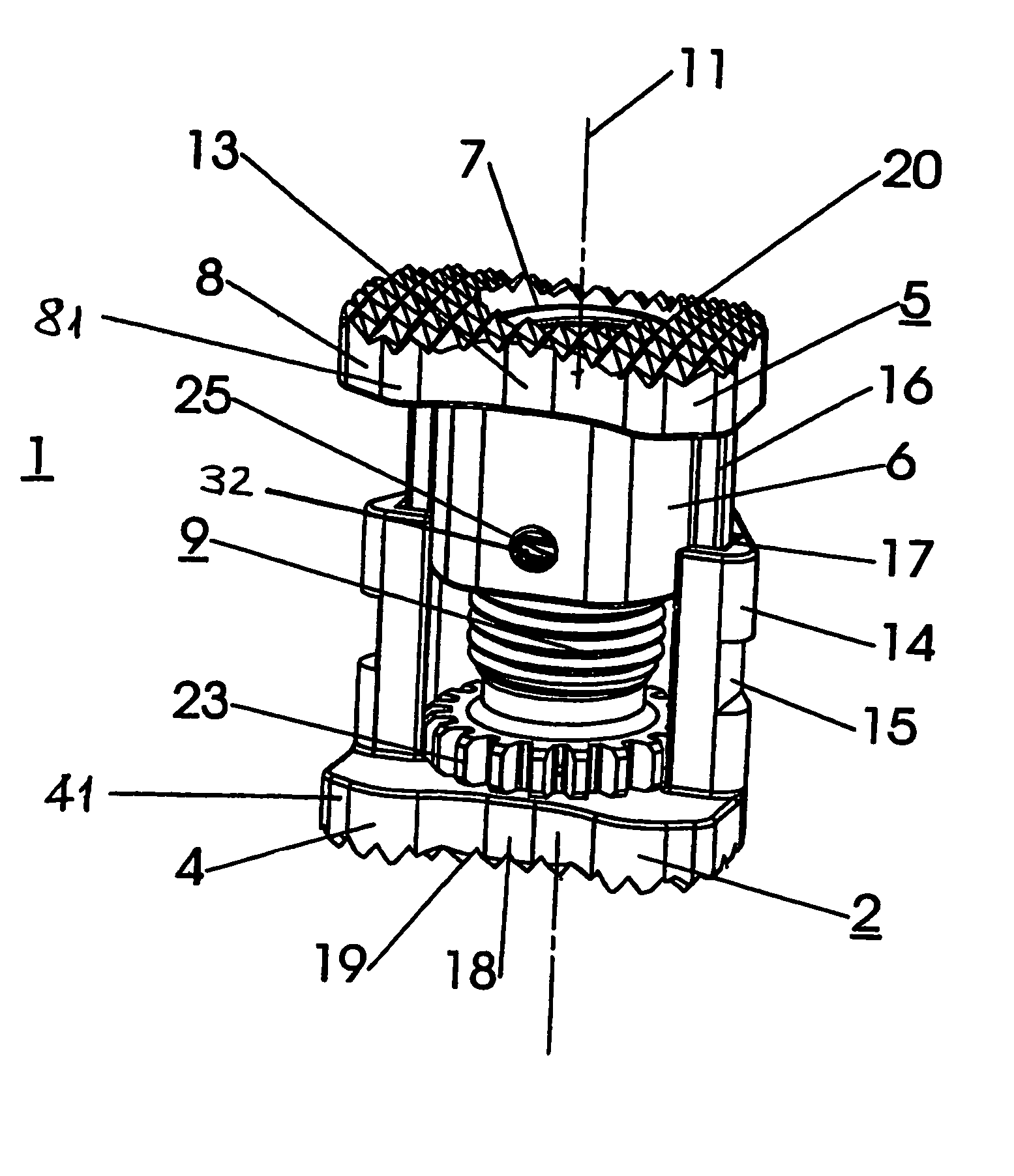
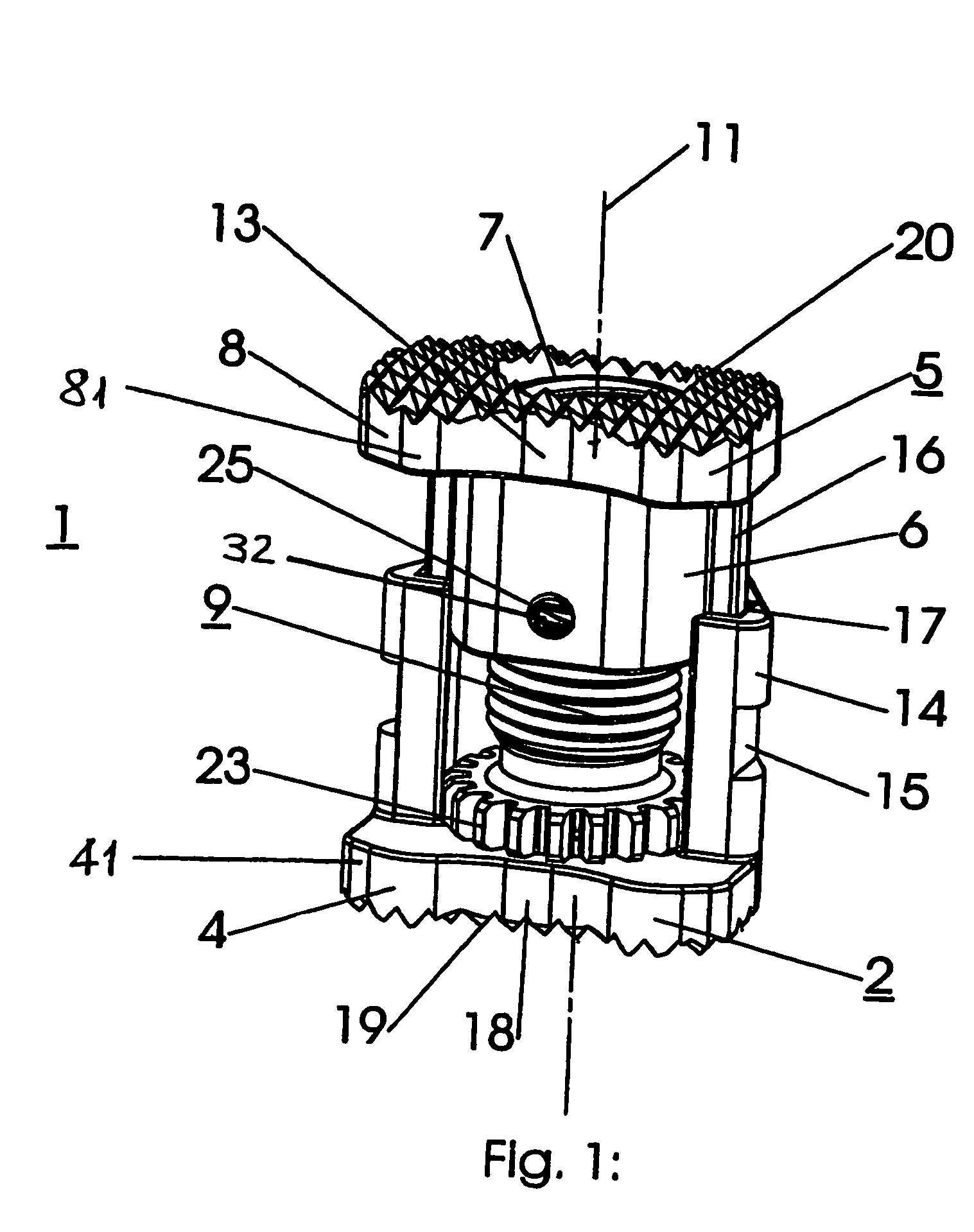
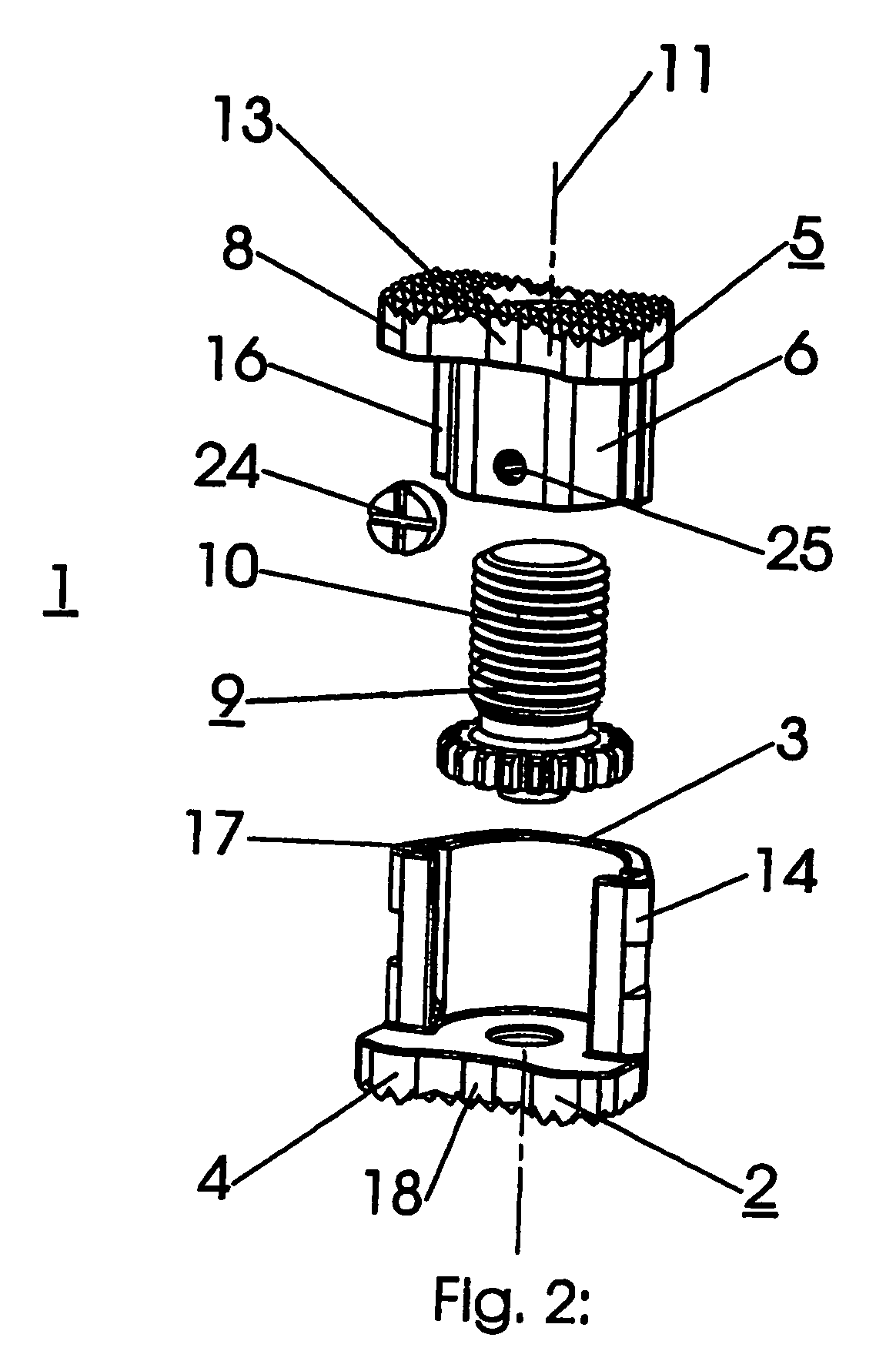
[0034]An embodiment of the intervertebral implant according to the invention is shown in FIGS. 1 to 6, which comprises a lower implant part 2 that is coaxial to the central axis 11, having an outside, lower apposition part 4, and an upper implant part 5 that is coaxial to the central axis 11, having an outside, upper apposition part 8. The lower apposition part 4 has an apposition surface 19 that stands crosswise to the central axis 11, which is intended to rest against the base surface of the vertebra adjacent towards the bottom. Analogously, the upper apposition part 8 has an apposit...


PUM


Abstract

An intervertebral implant comprising a lower implant part, having a central axis and an apposition section, designed to rest against the covering surface of the adjacent lower vertebra and an upper implant part comprising a bore with an internal thread, a central axis and an apposition section, designed to rest against the covering surface of the adjacent upper vertebra. Specifically, the lower and upper implant parts are secured in relation to each other against rotation about the central axis and a threaded screw with an external thread is guided in the upper implant part and connected to the lower implant part, the external thread cooperating with the internal thread. The lower and upper implant parts, and the threaded screw lie coaxially along their common central axis, the threaded screw being connected to the lower implant part so that it is axially fixed but able to rotate.

Description

CROSS REFERENCE TO RELATED APPLICATION[0001]This application is a continuation of International Patent Application No. PCT / CH2002 / 000674, filed Dec. 6, 2002, the entire contents of which is expressly incorporated herein by reference.FIELD OF THE INVENTION[0002]The invention relates generally to an intervertebral implant.BACKGROUND OF THE INVENTION[0003]An intervertebral implant is known from US-A 2002082695 NEUMANN. Here, the central implant part, configured as a threaded ring having an inside thread, is connected with the upper implant part that stands in the end position. The upper part of the lower implant part is structured with a conical surface that serves as an accommodation for the threaded ring. By means of a special instrument that has a bevel wheel that can be brought into engagement with the bevel wheel on the threaded ring, the threaded ring can be rotated about the central axis of the intervertebral implant and the upper implant part can be axially displaced. The threa...

Claims


Application Information

Patent Timeline
Patent Type & Authority Patents(United States)
IPC IPC(8): A61F2/44A61F2/00A61F2/30
CPCA61F2/44A61F2002/30383A61F2002/30405A61F2002/305A61F2002/30507A61F2220/0025A61F2002/3055A61F2002/30601A61F2002/30774A61F2002/30777A61F2002/30843A61F2002/30525
Inventor GUTLIN, MICHAELSCHAR, MANUEL
Owner SYNTHES USA
Why Eureka
Try Eureka