Inspection apparatus for optical disk having phase modulated wobble tracks and optical disk apparatus for driving the optical disk

a technology of optical disk and optical disk, which is applied in the direction of digital signal error detection/correction, instruments, recording signal processing, etc., can solve the problem of difficult evaluation of phase shift, and achieve the effect of enhancing the quality of wobble track, improving accuracy and high performan

Inactive Publication Date: 2010-04-13
TEAC CORP
View PDF11 Cites 2 Cited by
  • Summary
  • Abstract
  • Description
  • Claims
  • Application Information

AI Technical Summary

Benefits of technology

[0009]The present invention provides a method, an apparatus, and an optical disk, in which, in addition to frequency characteristics (CNR) of a wobble track which has been phase-modulated, phase characteristics (a phase shift) of the wobble track can also be evaluated, thereby allowing evaluation of the quality of the wobble track at a higher precision, or an optical disk apparatus with high performance address reading.
[0014]According to the present invention, the quality of a wobble track formed on an optical disk can be evaluated, and more particularly the CNR and the phase shift can be evaluated simultaneously, thereby allowing highly precise inspection as to whether a wobble track is normal or defective. Further, according to the present invention, it is possible to provide an optical disk on which a wobble track is formed at high precision for allowing high quality data recording and reproducing.

Problems solved by technology

It is therefore difficult to evaluate a phase shift only by the measurement of CNR of a doubled wobble signal using a spectrum analyzer.

Method used


Image

  • Inspection apparatus for optical disk having phase modulated wobble tracks and optical disk apparatus for driving the optical disk
  • Inspection apparatus for optical disk having phase modulated wobble tracks and optical disk apparatus for driving the optical disk
  • Inspection apparatus for optical disk having phase modulated wobble tracks and optical disk apparatus for driving the optical disk

Examples


Embodiment Construction

[0026]A preferred embodiment of the present invention will be described in detail with reference to the accompanying drawings.

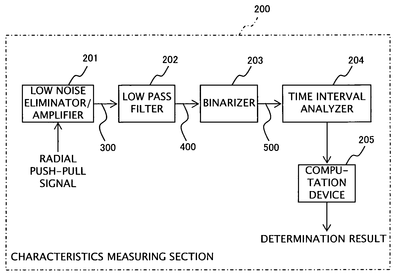
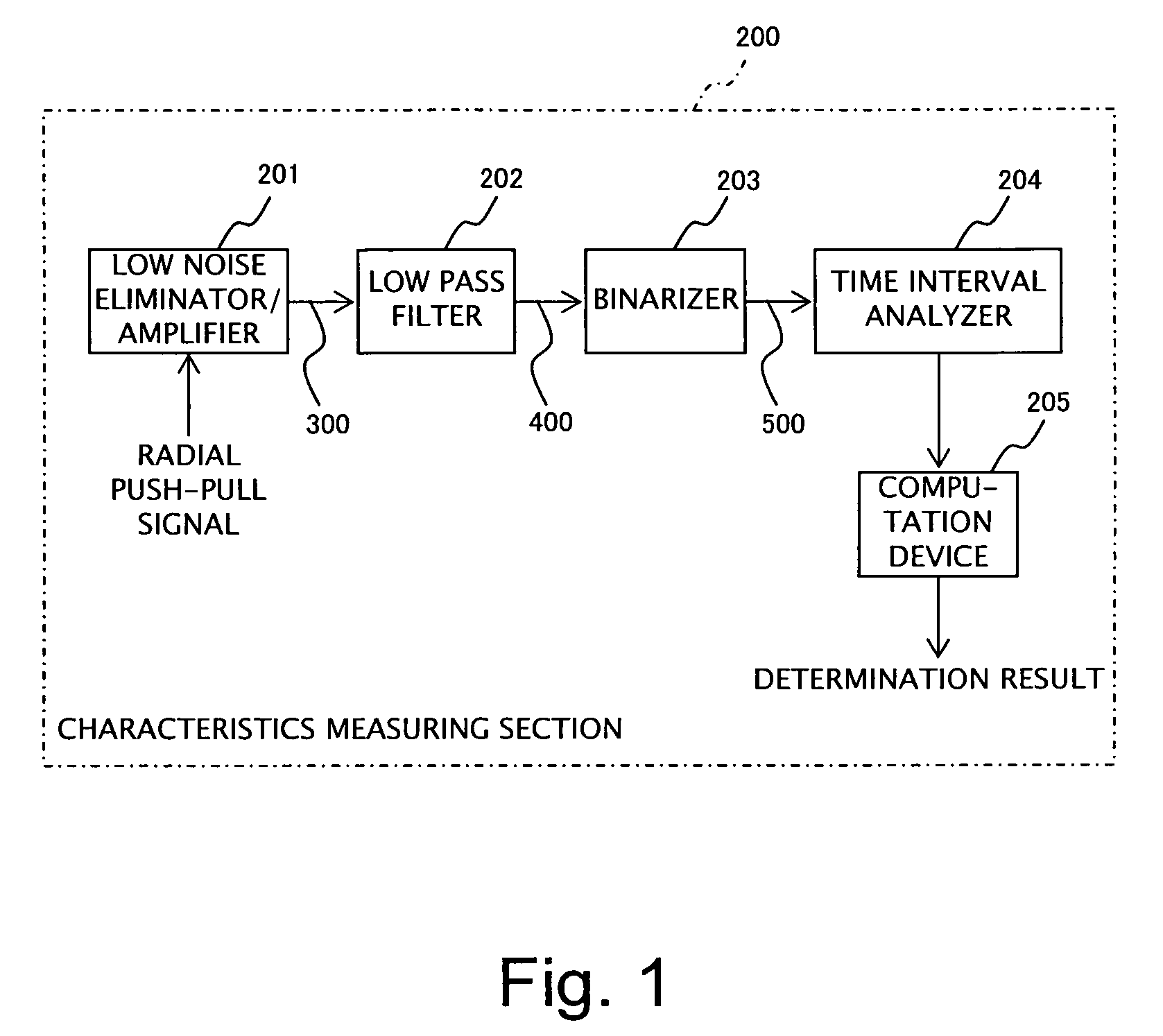
[0027]An overall structure of an optical disk inspection apparatus according to the present embodiment is substantially the same as that of a conventional apparatus shown in FIG. 7. More specifically, laser light is irradiated onto the optical disk D1 having a wobble track which has been subjected to BPSK (Binary Phase Shift Keying) modulation, such as DVD+R and DVD+RW. The light reflected from the optical disk D1 is received by the PD 50 and is converted into an electrical signal. After amplification of the electrical signal by the pre-amplifier 60, a radial push-pull signal is extracted as a wobble signal. While the wobble signal is then supplied to the frequency characteristics measuring section 100 in the structure shown in FIG. 7, the wobble signal is supplied to a characteristics measuring section 200 in the present embodiment.

[0028]FIG. 1 is a block di...


PUM

PropertyMeasurementUnit
frequencyaaaaaaaaaa
time interval analyzeraaaaaaaaaa
peak widthsaaaaaaaaaa

Abstract

An inspection apparatus for inspecting a phase modulated wobble track of an optical disk is provided. A radial push-pull signal (a wobble signal) of an optical disk is supplied to a low pass filter where a phase boundary portion of the wobble signal is smoothed, and then binarized by a binarizer and supplied to a time interval analyzer. The time interval analyzer analyzes a period of the binary wobble signal to extract two peak values T1 and T2 thereof. An operation device computes a difference value of the two periods T1 and T2 and a standard deviation of each peak, and compares each computed value to a threshold value for simultaneously evaluating CNR and a phase shift. The low pass filter and the binarizer may be incorporated into an optical disk apparatus for smoothing the phase boundary portion of the reproduced wobble signal.

Description

BACKGROUND OF THE INVENTION[0001]1. Field of the Invention[0002]The present invention relates to technology for inspecting an optical disk having a wobble track which has been phase-modulated, and to technology for reproducing data recorded on an optical disk.[0003]2. Description of Related Art[0004]Conventionally, a technique for inspecting an optical disk having wobble tracks which are wobbled in accordance with a frequency which is phase-modulated, such as DVD+R and DVD+RW, to determine whether or not the wobble tracks are formed correctly, has been proposed.[0005]Japanese Patent Laid-Open Publication No. 2004-280878 discloses that a light beam is irradiated onto a wobble track and a wobble signal obtained from light reflected from the wobble track is doubled, whereby the quality of the wobble track is evaluated based on the frequency characteristics of the doubled signal.[0006]FIG. 7 is a block diagram showing the structure of an evaluation device described in the above-describe...

Claims


Application Information

Patent Timeline
Patent Type & Authority Patents(United States)
IPC IPC(8): G11B7/24
CPCG11B7/0053G11B7/00G11B20/10G11B20/18
Inventor MASHIMO, AKIRAUENO, KEISHI
Owner TEAC CORP
Why Eureka
Try Eureka