Light-emitting device and image reading apparatus

a light-emitting device and image-reading technology, applied in lighting and heating devices, liquid/fluent solid measurements, instruments, etc., can solve problems such as breaking or damage residual chips, and achieve the effect of enhancing heat-releasing performance and small siz

Inactive Publication Date: 2010-05-18
NIPPON SHEET GLASS CO LTD +1
View PDF9 Cites 6 Cited by
  • Summary
  • Abstract
  • Description
  • Claims
  • Application Information

AI Technical Summary

Benefits of technology

[0011]In the present invention, the metallic part is held in contact with the light-guiding member and has a wave-like shape in cross section. With this arrangement, a surface area of the metallic part in a given region is increased so that heat releasing performance can be enhanced. The light-guiding member may have a portion having a shape matched with the wave-like shape of the metallic part so that the light-guiding member is more tightly held in contact with the metallic part, achieving more rigid connection therebetween.
[0034]With the above arrangement, a surface area of the metallic part in a given region is increased so that heat releasing performance can be enhanced. The light-guiding member may have a portion having a shape matched with the wave-like shape of the metallic part so that the light-guiding member is more tightly held in contact with the metallic part, providing an image reading apparatus with small size.

Problems solved by technology

The above described conventional light-emitting element 3000 poses a problem in that heat generated from one of the three semiconductor light-emitting element chips, which all are mounted on the first lead member 3210, may break or damage the residual chips.

Method used


Image

  • Light-emitting device and image reading apparatus
  • Light-emitting device and image reading apparatus
  • Light-emitting device and image reading apparatus

Examples


first embodiment

Light-Emitting Element

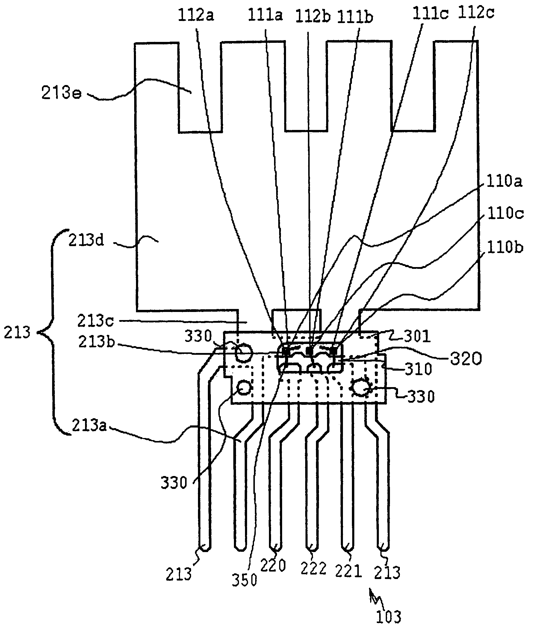
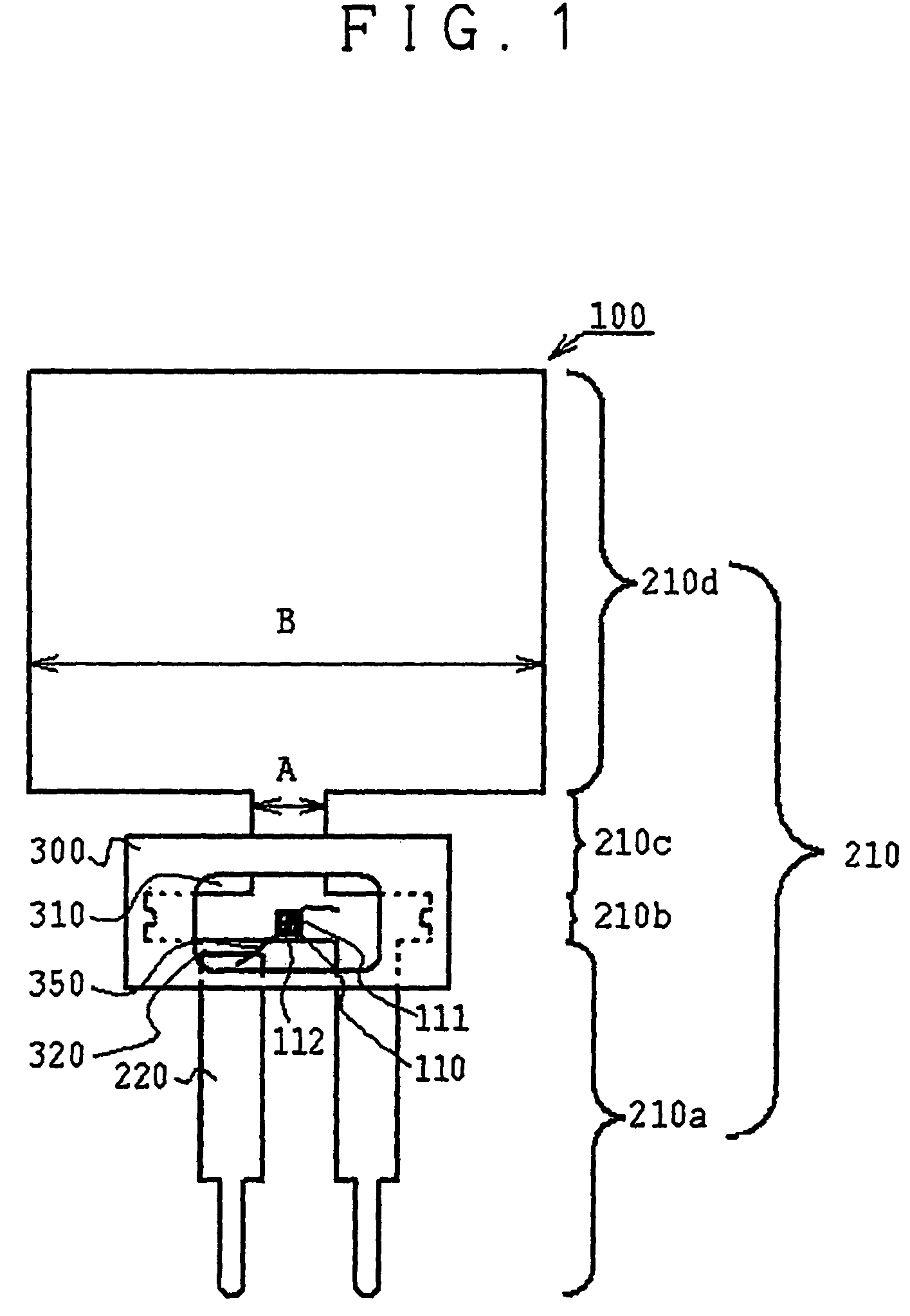
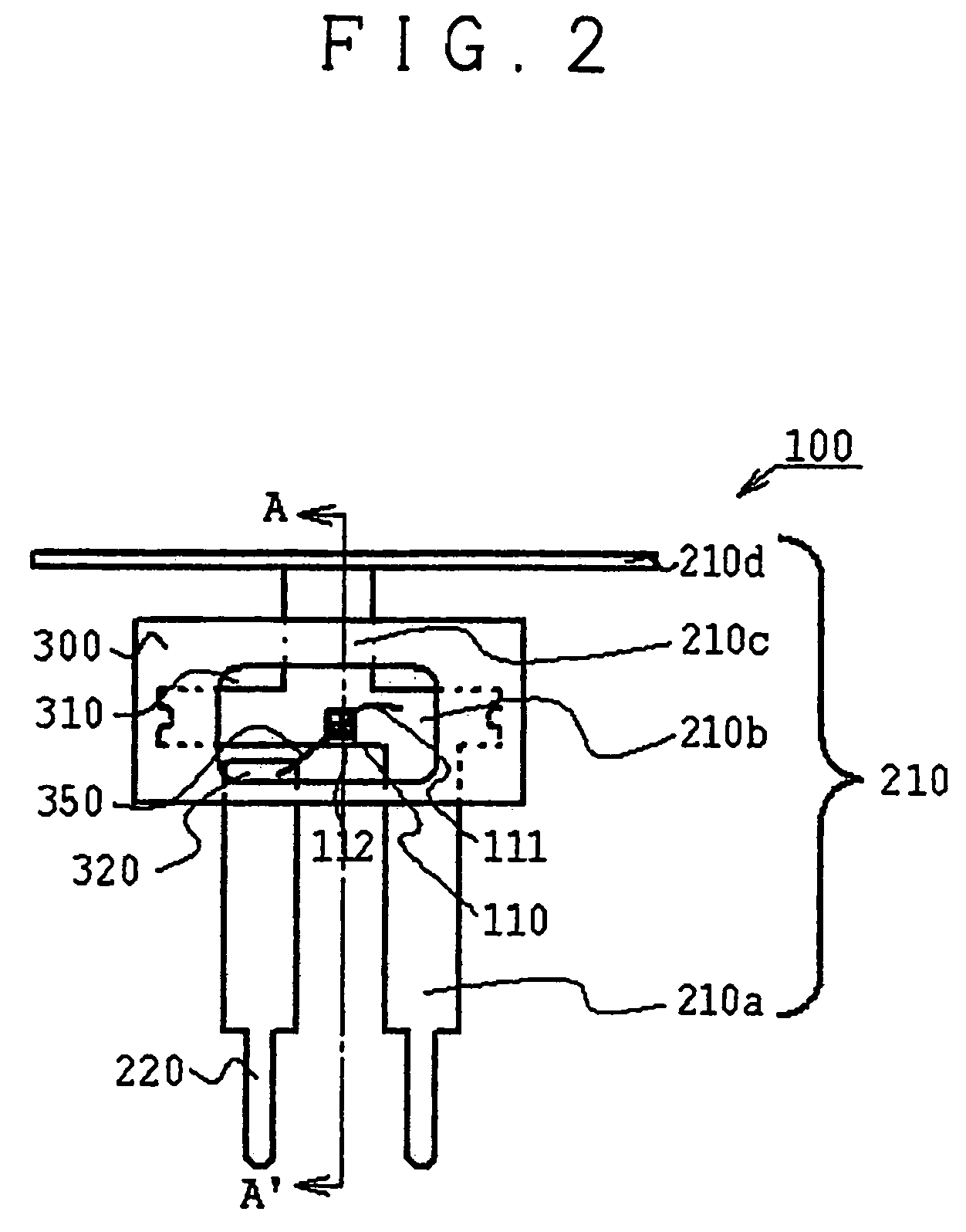
[0058]Now, the description will be made for a light-emitting element according to the first embodiment. FIG. 1 is a schematic plan view illustrating the light-emitting element of the first embodiment. FIG. 2 is a schematic plan view with a portion enlarged, which illustrates the light-emitting element of the first embodiment. FIG. 3 is a schematic cross sectional view (a sectional view taken along a line A-A in FIG. 2) according to the first embodiment. Specifically, FIG. 1 illustrates the light-emitting element before it is mounted to a light-emitting device, and FIGS. 2 and 3 each illustrate the light-emitting element having lead members bent when it is to be mounted to the light-emitting device.

[0059]A light-emitting element 100 of the first embodiment includes a semiconductor light-emitting element chip 110, a first lead member 210, a second lead member 220, and a molded member 300 on which the first lead member 210 and the second lead member 220 are fixedl...

second embodiment

[0080]Now, the description will be made for a light-emitting device according to the second embodiment with reference to the drawings attached hereto. FIG. 4 is a schematic cross sectional view illustrating the light-emitting device of the second embodiment. The detailed description for the members, parts and the like equivalent or corresponding to those of the light-emitting element of the first embodiment will be omitted.

[0081](Light-Emitting Device)

[0082]A light-emitting device 5000 includes a light-guiding member 400 having an end portion, to which the light-emitting element 100 is attached through the side in which the window 310 is formed. Light emitted from the light-emitting element 100 is incident onto the light-guiding member 400 through its end portion, repeatedly reflected and transmitted through the light-guiding member 400 and emitted to the outside in the lengthwise direction of the light-guiding member 400. Light may be emitted in one direction by changing the size (...

third embodiment

[0087]Now, the description will be made for a light-emitting device according to the third embodiment with reference to the drawings attached hereto. FIG. 5 is a schematic cross sectional view illustrating the light-emitting device of the third embodiment. FIG. 6 is a schematic top view illustrating the light-emitting device of the third embodiment. The detailed description for the members, parts and the like equivalent or corresponding to those of the light-emitting element of the first embodiment and the light-emitting device of the second embodiment will be omitted.

[0088]A light-emitting device 6000 has a light-guiding member 410, to which the light-emitting element 100 is attached. The light-guiding member 410 has a fitting part 410a, in which the molded member 300 and the metallic part 210d, of the light-emitting element 100 are to be fitted. The molded member 300 and the metallic part 210d, of the light-emitting element 100 are fitted in this fitting part 410a so as to achieve...


PUM


Abstract

A light-emitting device includes a light-emitting element and a light-guiding member for causing light from the light-emitting element entering into it through one surface thereof. The light-emitting element includes a lead member with a light-emitting element chip mounted thereon and a molded member to which the lead member is secured. The lead member has a metallic part extending from the molded member, and the metallic part is bent. The thus arranged light-emitting device has an excellent heat release capability. An image reading apparatus using the light-emitting device is also provided.

Description

CROSS REFERENCE TO RELATED APPLICATION[0001]This application claims priority from Japanese Patent Application No. 2005-086291, which is incorporated herein by reference.BACKGROUND OF THE INVENTION[0002]1. Field of the Invention[0003]The present invention relates to a light-emitting device and an image reading apparatus.[0004]2. Related Art[0005]Hitherto, an image reading apparatus (a contact image sensor) is used as an apparatus for reading a document image or the like in a facsimile machine, a copy machine, an image scanner, etc. The image reading apparatus includes a light-emitting device that irradiates light linearly along the main-scanning direction onto a surface of a document, and this light-emitting device in turn includes a transparent light-guiding member having a bar- or plate-like shape with a longitudinal axis. Light incident onto an end surface of the transparent light-guiding member is reflected and transmitted therethrough, and emitted to the outside from an emission...

Claims


Application Information

Patent Timeline
Patent Type & Authority Patents(United States)
IPC IPC(8): H01L27/15H01L29/26H01L31/12H01L33/00F21V29/00H01L33/32H01L33/62H01L33/64
CPCH04N1/00989H04N1/02815H04N1/02835H04N2201/03112H01L2224/48091H01L2224/48247H01L2224/48257H04N2201/03125H04N2201/03141H04N2201/03145H01L2924/00014H01L2924/181H01L2924/00012G01F15/06G01F3/22
Inventor SUGIMOTO, KUNIHITOSUMITANI, NAOFUMIWAKISAKA, MASAHIDE
Owner NIPPON SHEET GLASS CO LTD
Why Eureka
Try Eureka