Axial fan assembly

a technology of axial fans and blades, which is applied in the direction of liquid fuel engines, vessel construction, marine propulsion, etc., can solve the problems of reducing the efficiency of the tip of the axial fan blade to generate pressure, the inward radial inflow velocity is relatively high near the tip of the axial fan blade, and the design goal is complicated. , to achieve the effect of low noise and high efficiency

Active Publication Date: 2010-07-27
ROBERT BOSCH CORP +1
View PDF41 Cites 18 Cited by
  • Summary
  • Abstract
  • Description
  • Claims
  • Application Information

AI Technical Summary

Benefits of technology

[0004]Axial fan assemblies utilized in automotive applications must operate with high efficiency and low noise. However, various constraints often complicate this design goal. Such constraints may include, for example, limited spacing between the axial fan and an upstream heat exchanger (i.e., “fan-to-core spacing”), aerodynamic blockage from engine components immediately downstream of the axial fan, a large ratio of the area of shroud coverage to the swept area of the axial fan blades (i.e., “area ratio”), and recirculation between the band of the axial fan and the shroud.
[0005]Several factors can contribute to decreasing the efficiency of the axial fan. A large area ratio combined with a small fan-to-core spacing usually results in relatively high inward radial inflow velocities near the tips of the axial fan blades. Airflow in this region also often mixes with a recirculating airflow around the band. Such a recirculating airflow around the band can have a relatively high degree of “pre-swirl,” or a relatively high tangential velocity in the direction of rotation of the axial fan. These factors, considered individually or in combination, often decrease the ability of the tips of the axial fan blades to generate pressure efficiently.

Problems solved by technology

However, various constraints often complicate this design goal.
A large area ratio combined with a small fan-to-core spacing usually results in relatively high inward radial inflow velocities near the tips of the axial fan blades.
These factors, considered individually or in combination, often decrease the ability of the tips of the axial fan blades to generate pressure efficiently.

Method used


Image

  • Axial fan assembly
  • Axial fan assembly
  • Axial fan assembly

Examples


Embodiment Construction

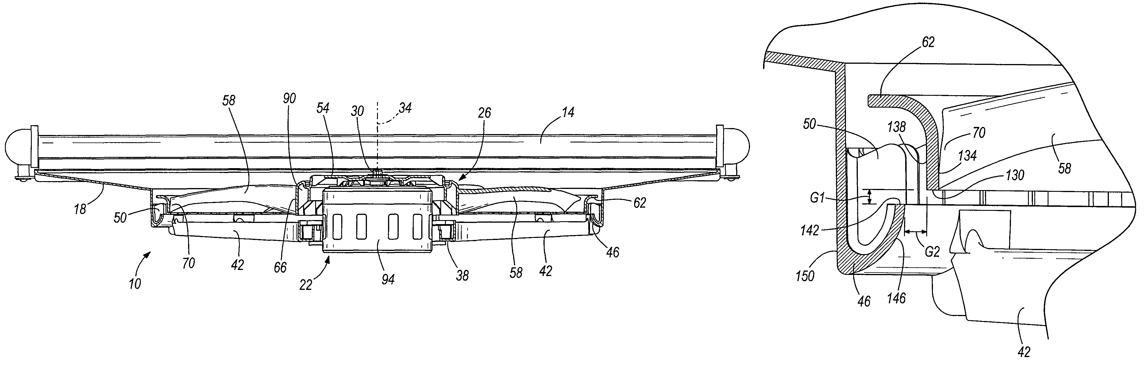
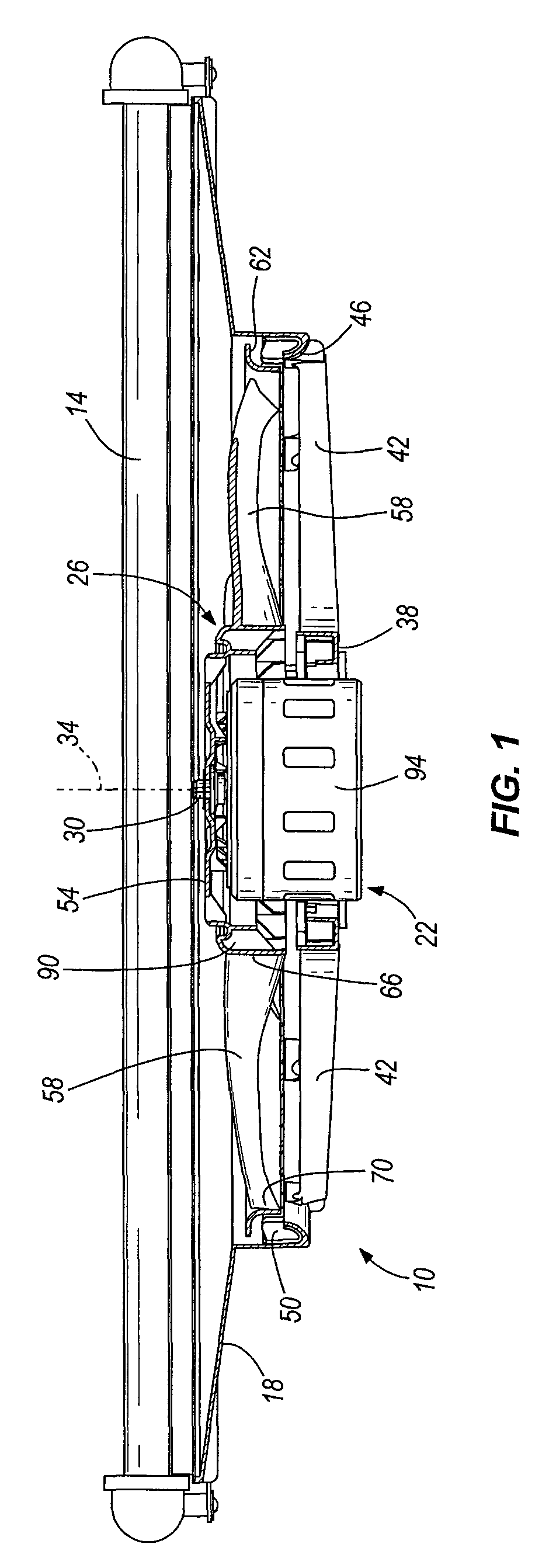
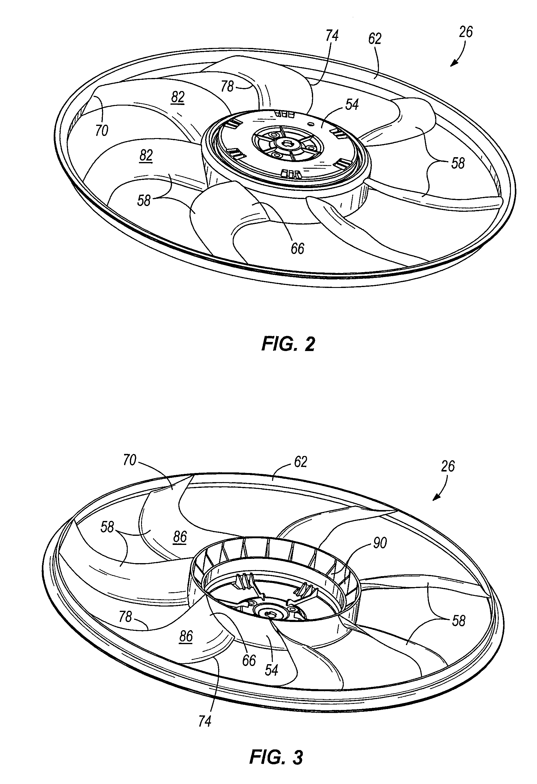
[0020]FIG. 1 illustrates an axial fan assembly 10 coupled to a heat exchanger 14, such as an automobile radiator. However, the axial fan assembly 10 may be utilized in combination with the heat exchanger 14 in any of a number of different applications. The axial fan assembly 10 includes a shroud 18, a motor 22 coupled to the shroud 18, and an axial fan 26 coupled to and driven by the motor 22. Particularly, as shown in FIG. 1, the motor 22 includes an output shaft 30 for driving the axial fan 26 about a central axis 34 of the output shaft 30 and the axial fan 26.

[0021]The axial fan assembly 10 is coupled to the heat exchanger 14 in a “draw-through” configuration, such that the axial fan 26 draws an airflow through the heat exchanger 14. Alternatively, the axial fan assembly 10 may be coupled to the heat exchanger 14 in a “push-through” configuration, such that the axial fan 10 discharges an airflow through the heat exchanger 14. Any of a number of different connectors may be utilize...


PUM


Abstract

The present invention provides an axial fan assembly including a motor having an output shaft rotatable about a central axis and a shroud coupled to the motor. The shroud includes a substantially annular outlet bell centered on the central axis. The axial fan assembly also includes an axial fan having a hub coupled to the output shaft for rotation about the central axis, a plurality of blades extending radially outwardly from the hub and arranged about the central axis, a substantially circular band coupled to the tips of the blades, and a plurality of leakage stators positioned radially outwardly from the band and adjacent the outlet bell.

Description

RELATED APPLICATIONS[0001]This application claims priority to U.S. Provisional Patent Application No. 60 / 803,576 filed May 31, 2006, the entire content of which is hereby incorporated by reference.FIELD OF THE INVENTION[0002]The present invention relates to axial fans, and more particularly to automotive axial fan assemblies.BACKGROUND OF THE INVENTION[0003]Axial fan assemblies, when utilized in an automotive application, typically include a shroud, a motor coupled to the shroud, and an axial fan driven by the motor. The axial fan typically includes a band connecting the respective tips of the axial fan blades, thereby reinforcing the axial fan blades and allowing the tips of the blades to generate more pressure.SUMMARY OF THE INVENTION[0004]Axial fan assemblies utilized in automotive applications must operate with high efficiency and low noise. However, various constraints often complicate this design goal. Such constraints may include, for example, limited spacing between the axia...

Claims


Application Information

Patent Timeline
Patent Type & Authority Patents(United States)
IPC IPC(8): F04D29/52
CPCF04D29/386F04D29/326F04D29/164F04D29/58F04D29/16F04D29/38F04D29/547
Inventor STEVENS, WILLIAMSTAIRS, ROBERT W.
Owner ROBERT BOSCH CORP
Why Eureka
Try Eureka