Apparatus and method for calibrating focus balance in an optical disk drive

a technology of optical disk drive and focus balance, which is applied in the field of optical disk drive, can solve the problems of not being able to directly output the optical disk drive, needs modulation, and cannot ensure the locking of the focus spot, and achieve the effect of enhancing the total performance of the disk driv

Inactive Publication Date: 2010-08-03
QUANTA STORAGE INC
View PDF5 Cites 0 Cited by
  • Summary
  • Abstract
  • Description
  • Claims
  • Application Information

AI Technical Summary

Benefits of technology

[0006]An objective of the present invention is to provide an apparatus for calibrating focus balance in an optical disk drive, wherein a jitter frequency is generated by a jitter generator, and the convergence of the jitter frequency is checked by a focus balance unit for calibrating focus balance, thereby enhancing the total performance in the disk drive.
[0007]Another objective of the present invention is to provide a method for calibrating focus balance in an optical disk drive, which rapidly achieves an appropriate focus balance by examining the convergence of the sequential jitter signals for calibrating the variable and direction of focus balance.

Problems solved by technology

However, since the focus spot is a small region of short distance, the aforementioned focus spot locked by focus calibration might not be the location of the strongest radio frequency signal RF.
Also, the aforementioned focus calibration employs a small electrical signal as means for determination, which is susceptible to the errors of the disk drive itself such as the non-uniformity of the light beam projected by the laser light source, the precision of the optical system, or the heterogeneity of the light receiving materials forming the four light receiving sections of the photodetector 4, leading to difficulty in ensuring locking of the focus spot.
However, the single radio frequency signal RF only represents a mark of binary code 1 or 0, which still needs modulation and cannot be directly output by the optical disk drive.
Sometimes, in the course of seeking the strongest radio frequency signal RF, the focus calibration tends to result in obscurity of some marks in a group of digital signals and leads to failure in demodulation.
Therefore, the method for seeking the strongest radio frequency signal RF still fails to effectively enhance the whole performance of the optical disk drive.
Accordingly, there are still problems to be solved in the conventional method for calibrating focus balance in a disk drive.

Method used


Image

  • Apparatus and method for calibrating focus balance in an optical disk drive
  • Apparatus and method for calibrating focus balance in an optical disk drive
  • Apparatus and method for calibrating focus balance in an optical disk drive

Examples


Embodiment Construction

[0014]The techniques employed by the present invention to achieve the above objectives and the effects thereof are described hereinafter by way of preferred embodiments in combination with the accompanying drawings.

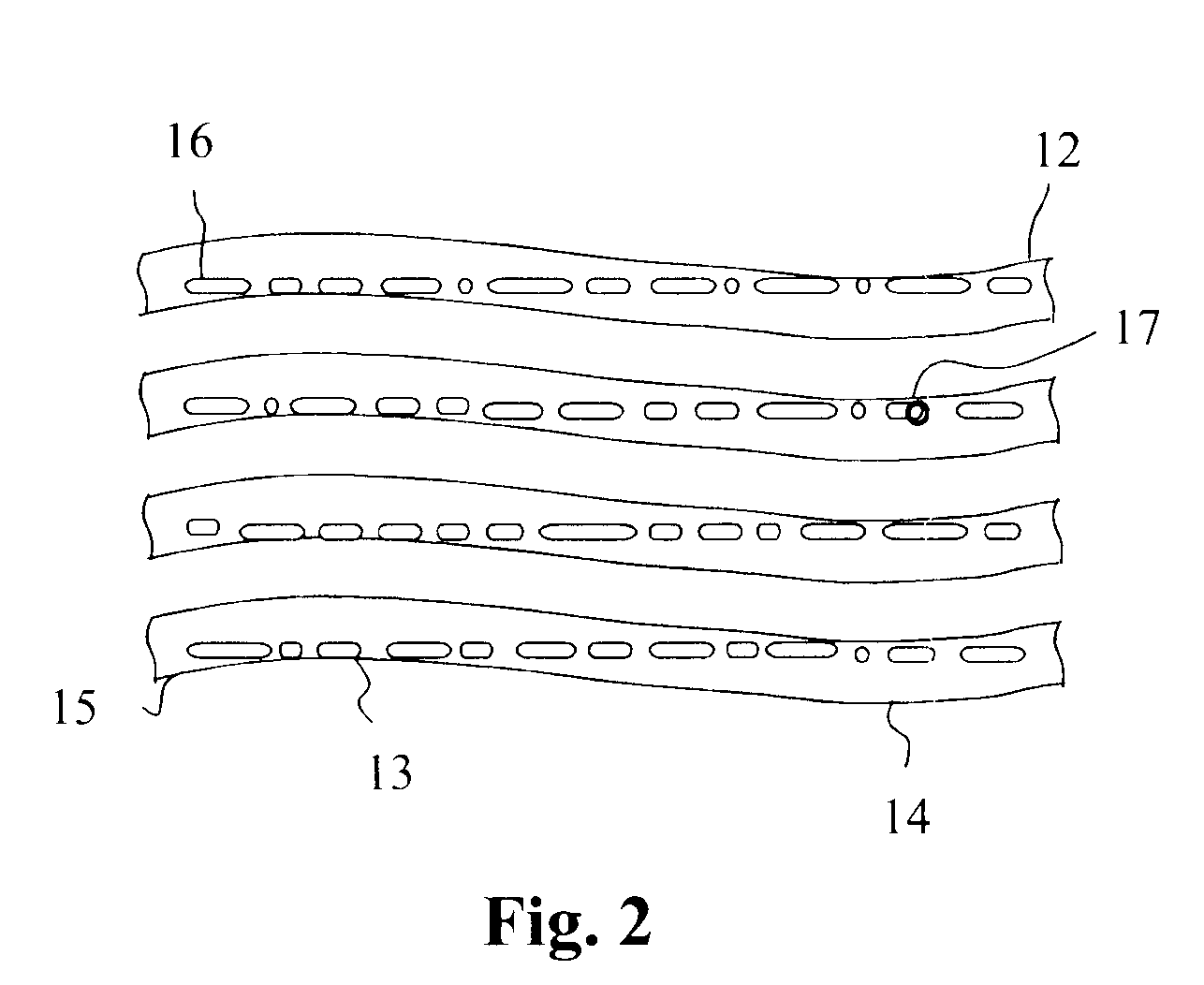
[0015]Referring to FIG. 2, the ordinary optical disk includes a spiral track 12 from the inside to the outside. The track 12 is a groove that the two sides of which become a peak 13 and a valley 14 with constant frequencies to form a wave edge 15. The data mark 16 modulated by EFM is spirally scribed in the groove of the track 12. As a result, the data mark 16 regularly and alternately approaches the wave edge 15 in turn and the laser spot 17 projected by the optical disk drive reads along the data mark 16 one by one with tracking-servo.

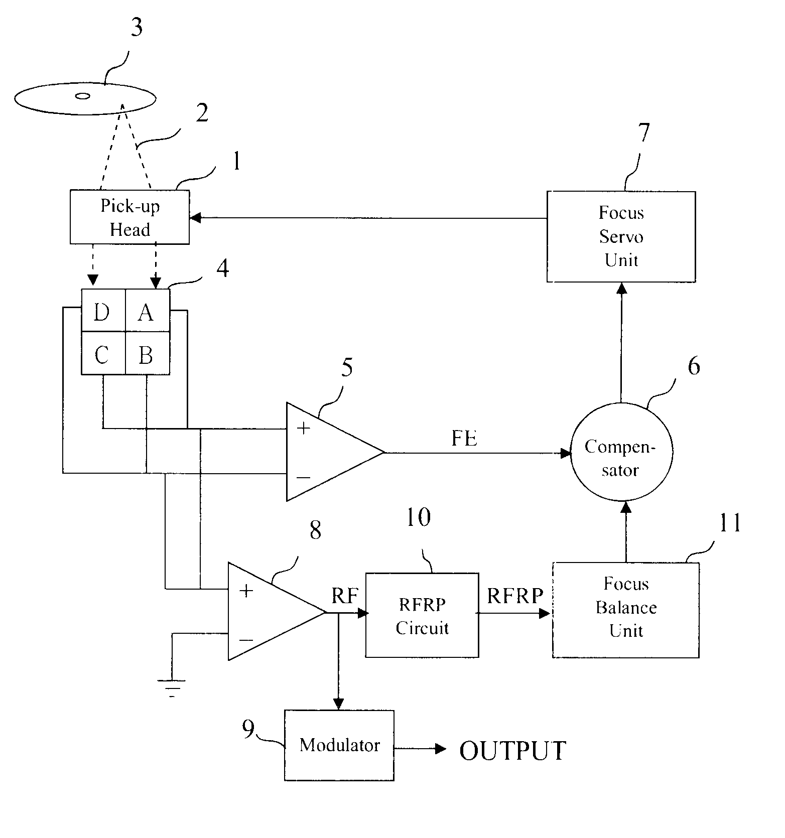
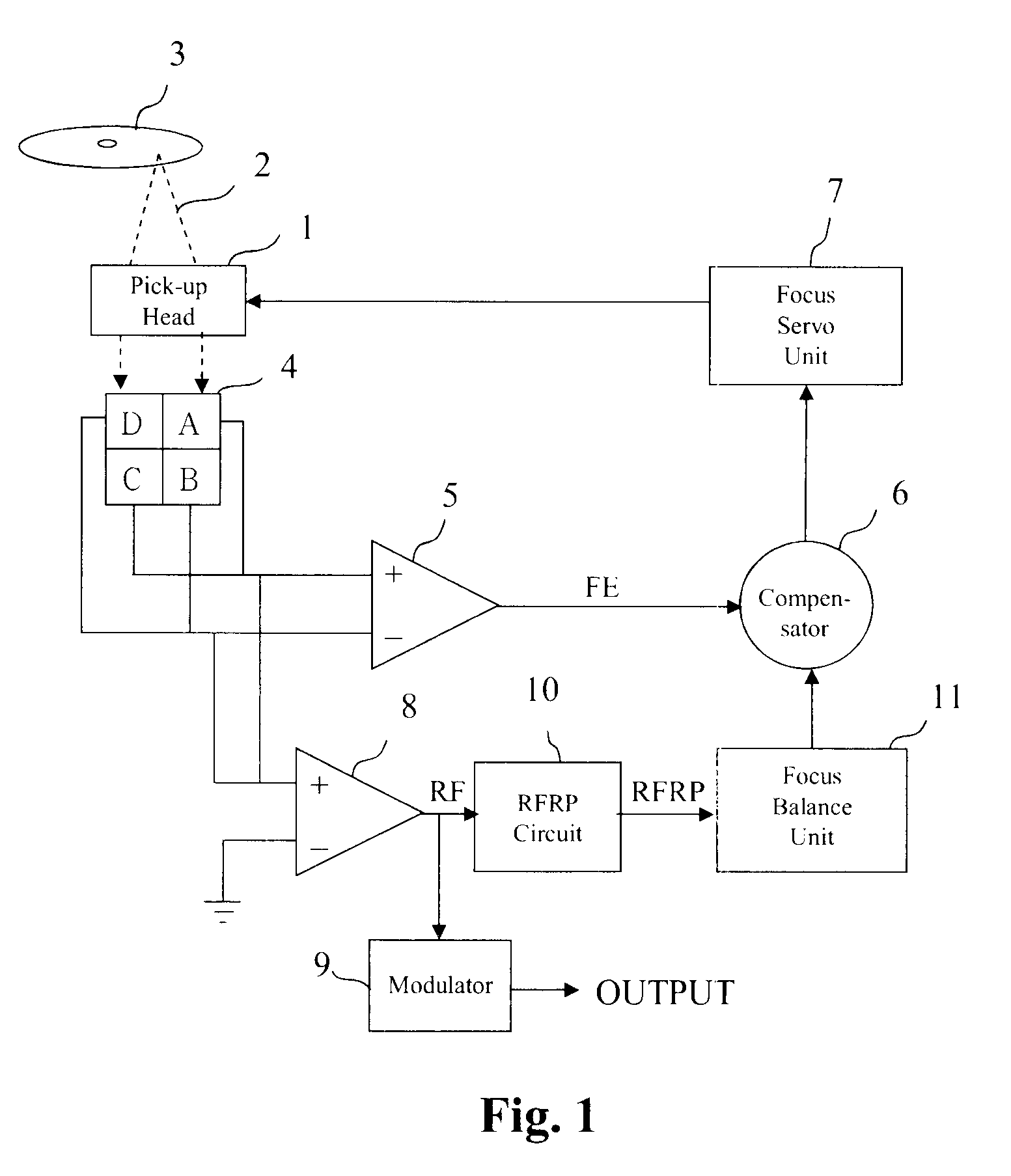
[0016]When the laser spot 17 strikes the data mark 16, the photodetector in the pick-up head receives the light reflected by the data mark 16 (refer to FIG. 1). The photodetector forms two sections, an upper section (A+C) and a lower secti...


PUM

PropertyMeasurementUnit
jitter frequencyaaaaaaaaaa
jitter frequenciesaaaaaaaaaa
electrical signalaaaaaaaaaa

Abstract

The present invention is to provide an apparatus and method for calibrating focus balance in an optical disk drive. A focus servo unit controls a pick-up head to focus and read a mark for generating an RF signal. A jitter generator separates a jitter signal from the RF signal to form a jitter frequency. A focus balance unit compares sequential jitter frequencies to check the convergence and the goal, and determines the direction and variable of calibrating focus balance to generate an error signal. A compensator receives the error signal through the focus servo unit to control the pick-up head for calibrating focus balance.

Description

FIELD OF THE INVENTION[0001]The present invention relates to an optical disk drive, in particular to an apparatus and method for calibrating focus balance in an optical disk drive with jitter frequencies.BACKGROUND OF THE INVENTION[0002]Since data are recorded on an optical disk with dense minute marks, an optical disk drive must use an optical pick-up head to project laser light focused on the marks and convert the magnitude of the light reflected by the marks into a digital signal which is then decoded into a data signal. Therefore, the accuracy of focus may directly influence the magnitude of the received signal and the correctness of data.[0003]As shown in FIG. 1, a conventional method for calibrating focus balance in an optical drive which employs a pick-up head 1 to project a light beam 2 onto a optical disk 3, and the optical disk 3 reflects the light beam 2 onto a photodetector 4 through the pick-up head 1. The photodetector 4 has four equally divided light receiving section...

Claims


Application Information

Patent Timeline
Patent Type & Authority Patents(United States)
IPC IPC(8): G11B7/125
CPCG11B7/0945G11B7/094
Inventor YANG, HUNG-PINHUANG, WEI-TINGHUANG, SHIH-JUNG
Owner QUANTA STORAGE INC
Why Eureka
Try Eureka