Vehicle barrier system

a technology of vehicle arresting and barrier system, which is applied in roadway safety arrangements, roads, construction, etc., can solve the problems of requiring substantial ground preparation, utility relocation and construction effort, and currently available devices, and achieve the effect of increasing the vehicle arresting function of the barrier system

Inactive Publication Date: 2010-08-17
DARCY DANIEL T
View PDF56 Cites 31 Cited by
  • Summary
  • Abstract
  • Description
  • Claims
  • Application Information

AI Technical Summary

Benefits of technology

[0005]It is a further object of this invention to provide such an improved vehicle barrier system which requires much less ground preparation.
[0007]It is a further object of this invention to provide such an improved vehicle barrier system which admits of easy and aesthetic variations in design and appearance.
[0008]It is a further object of this invention to provide such an improved vehicle barrier system which permits easy integration of common landscape items such as park benches, bus waiting shelters, vehicular gates, pedestrian gates, street lighting, fountains, civic art and sculpture, trash receptacles, tables, chairs, and other exterior elements which may disguise and increase the vehicle arresting function of the barrier system.

Problems solved by technology

The presently available devices suffer from one or more disadvantages including being generally complex and expensive, and requiring substantial ground preparation, earth moving, utility relocation and construction effort.
The process requires costly underground utility relocation (most utilities are located 36″ to 48″ below grade).
This is a time consuming and costly process in an urban setting.
Thus not allowing the installation of bollards in that area.
Whether these simpler approaches are used or more complex approaches are used the flexibility of design is severely limited: architectural and aesthetic qualities are generally sacrificed for security.

Method used


Image

  • Vehicle barrier system
  • Vehicle barrier system
  • Vehicle barrier system

Examples


Embodiment Construction

[0030]Aside from the preferred embodiment or embodiments disclosed below, this invention is capable of other embodiments and of being practiced or being carried out in various ways. Thus, it is to be understood that the invention is not limited in its application to the details of construction and the arrangements of components set forth in the following description or illustrated in the drawings. If only one embodiment is described herein, the claims hereof are not to be limited to that embodiment. Moreover, the claims hereof are not to be read restrictively unless there is clear and convincing evidence manifesting a certain exclusion, restriction, or disclaimer.

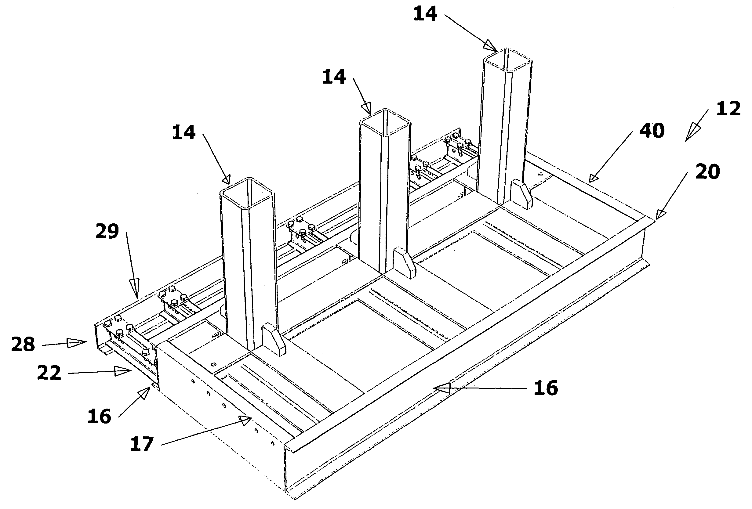
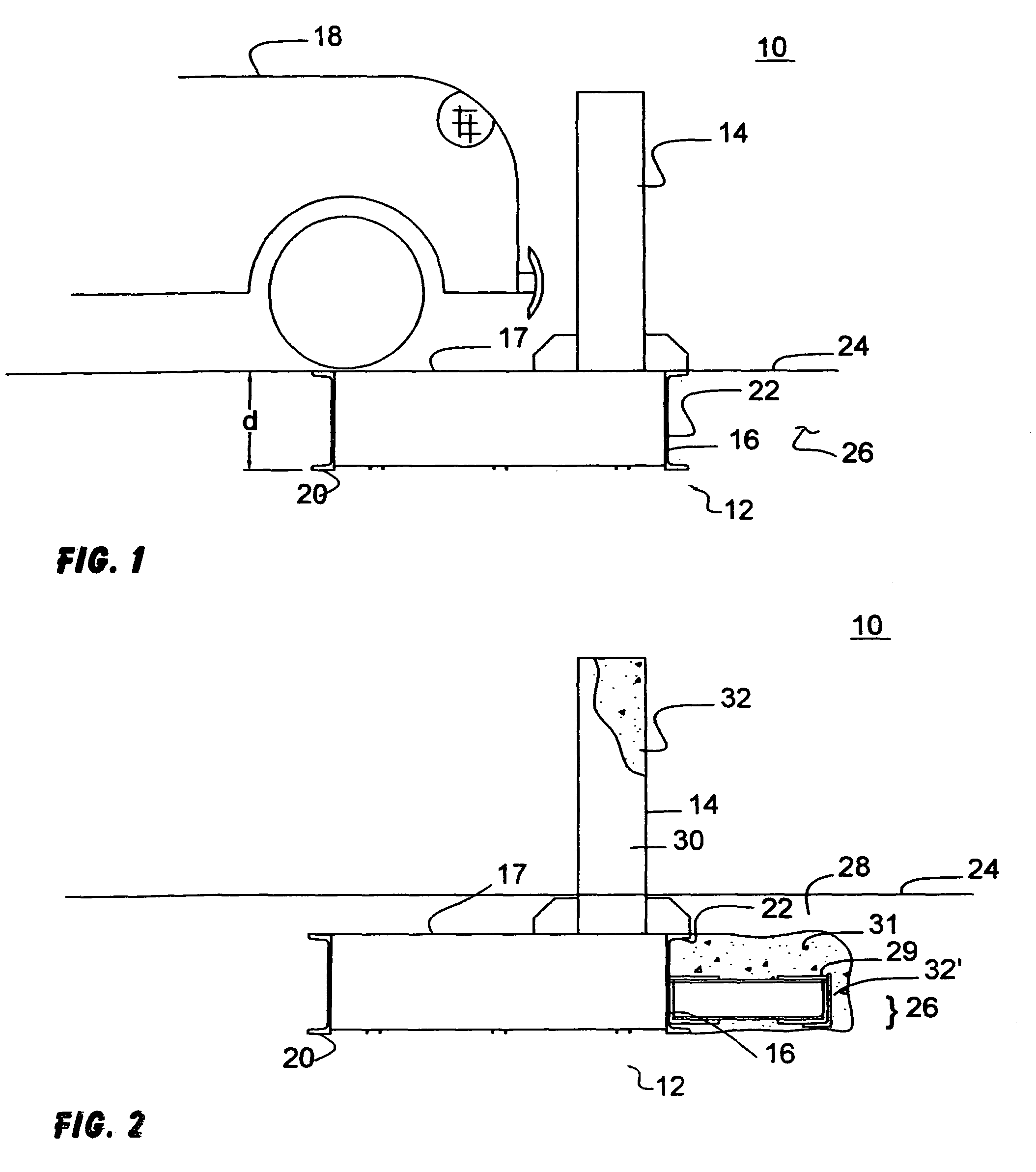
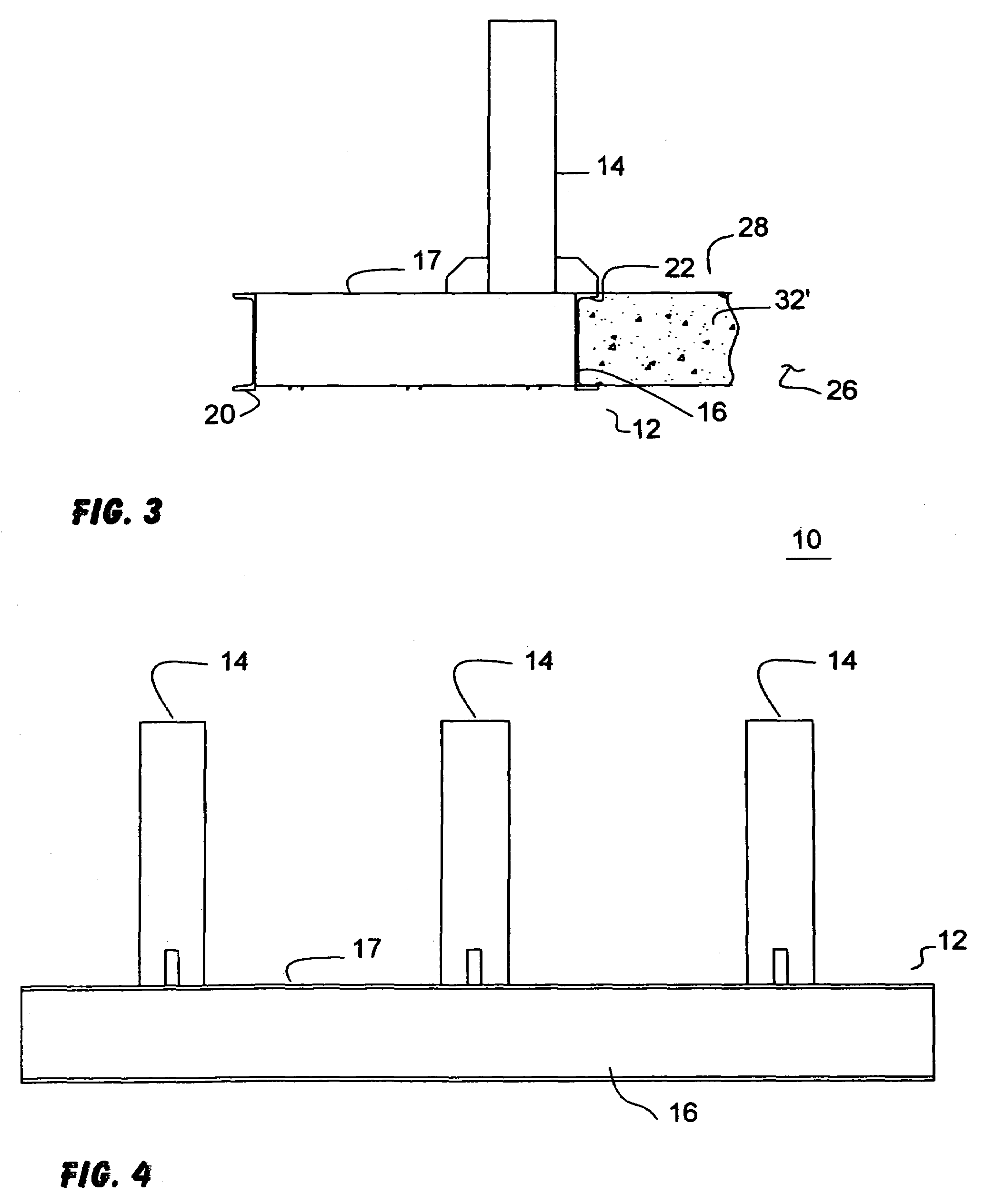
[0031]There is shown in FIG. 1 a vehicle barrier system 10 according to this invention including a reaction mass 12 for installation in the earth and at least one post 14 immovably anchored in reaction mass 12 and extending upwardly therefrom. Reaction mass 12 includes a forward member 16 for confronting and compressing the...


PUM


Abstract

A modular vehicle barrier system includes a reaction mass for installation in the earth; at least one post immovably anchored in the reaction mass and extending upwardly therefrom; the reaction mass having a forward member for confronting and compressing the surrounding earth and absorbing energy from the impact of the vehicle with the post.

Description

RELATED APPLICATIONS[0001]This application is a continuation-in-part application of U.S. patent application Ser. No. 11 / 054,257, filed Feb. 9, 2005 now abandoned, entitled “Vehicle Barrier System”. This application claims benefit of U.S. patent application Ser. No. 11 / 054,257, filed Feb. 9, 2005 and U.S. Provisional Application No. 60 / 621,374 filed Oct. 22, 2004, entitled “Assault Vehicle Barrier System” incorporated by reference herein.FIELD OF THE INVENTION[0002]This invention relates to a vehicle barrier system.BACKGROUND OF THE INVENTION[0003]With the rise in terrorism there has been a rise in the need for security and protection devices to defend buildings and facilities from attack by assault vehicles such as cars and trucks loaded with explosives. The presently available devices suffer from one or more disadvantages including being generally complex and expensive, and requiring substantial ground preparation, earth moving, utility relocation and construction effort. One of th...

Claims


Application Information

Patent Timeline
Patent Type & Authority Patents(United States)
IPC IPC(8): E01F13/00
CPCE01F13/12
Inventor DARCY, DANIEL T.
Owner DARCY DANIEL T
Why Eureka
Try Eureka