Spinal fusion cage and method of use

a fusion cage and spine technology, applied in the field of expandable fusion cages, can solve the problems of insufficient stability of the anterior approach to the spinal fusion, blood vessels, and disadvantages of the procedur

Inactive Publication Date: 2010-08-24
ABERNATHIE DENNIS LEE
View PDF10 Cites 226 Cited by
  • Summary
  • Abstract
  • Description
  • Claims
  • Application Information

AI Technical Summary

Problems solved by technology

Although ALIF is common, the procedure suffers from disadvantages.
In cases where patients have a “tall” disc, or where there is instability (such as with isthmic spondylolistheses), an anterior approach to the spinal fusion may not provide adequate stability.
Further, the procedure is performed in close proximity to the large blood vessels that go to the legs, thereby risking damage to these blood vessels, which can result in excessive blood loss.
In dealing with male patients, another unique risk arises.
A problem common to many fusion cages, regardless of method of insertion, concerns maintaining or restoring the normal anatomy of the fused spinal segment.
Such cages may lead to a kyphotic deformity as the vertebrae settles around the implant.
Fusion cages have been designed having a wedge-like shape in order to address these issues, but because of the shape of the cage, such devices must heretofore have been implanted using an ALIF procedure, thereby suffering from all of the disadvantages of using that procedure.
A problem with existing titanium cages is that it is difficult to assess spinal fusions postoperatively because the metal of the cage interferes with attempts to evaluate the fusion by x-ray.
A problem with such cages, however, is that they do not adhere well to the bony endplates and thus often must be supplemented with pedicle screws.

Method used


Image

  • Spinal fusion cage and method of use
  • Spinal fusion cage and method of use
  • Spinal fusion cage and method of use

Examples


Embodiment Construction

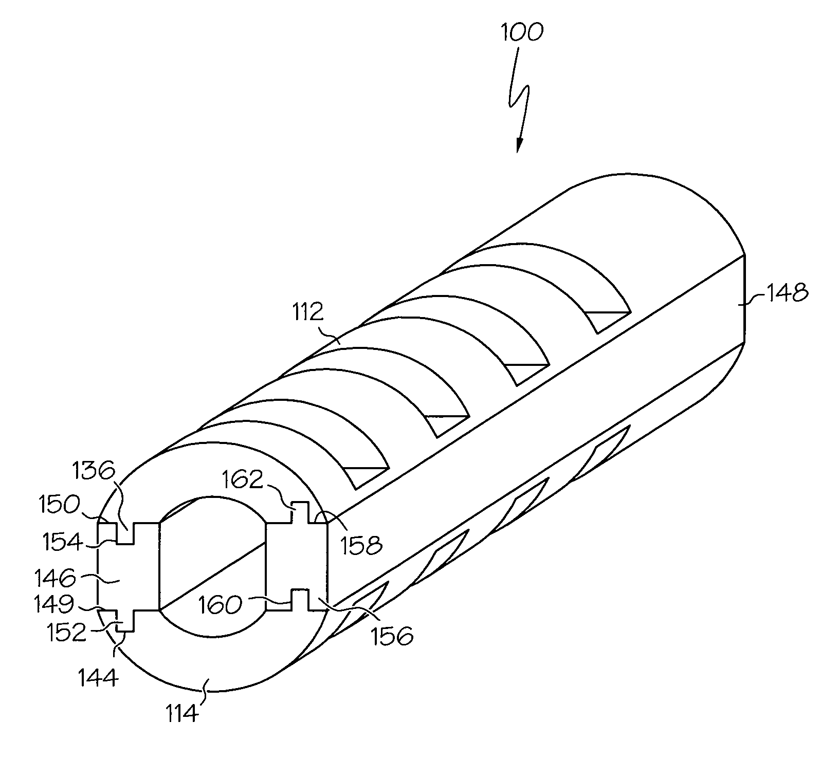
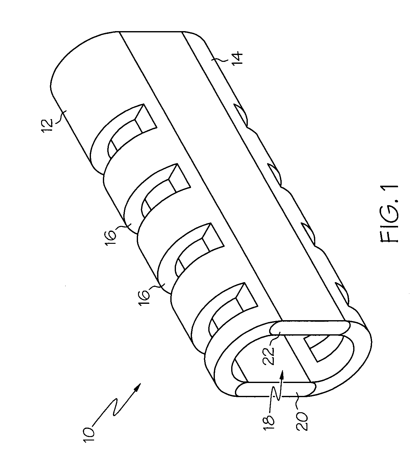
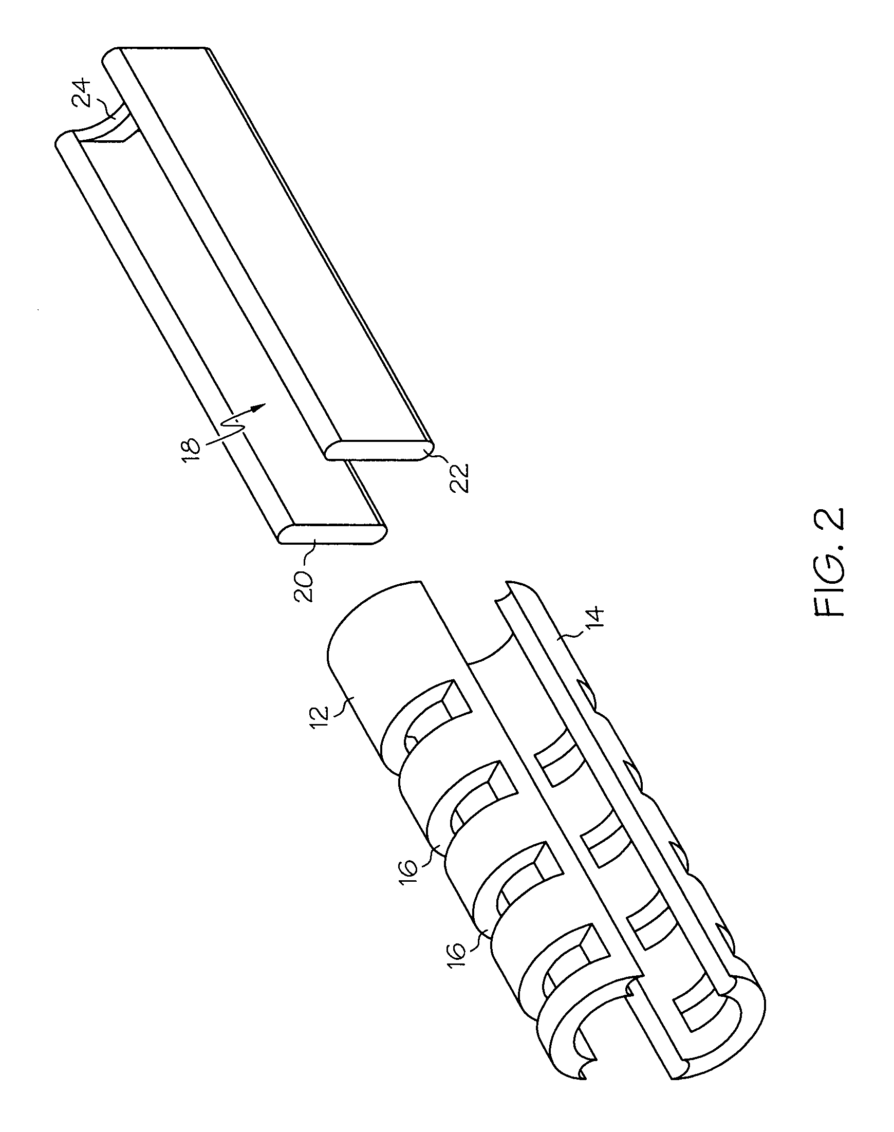
[0022]The several embodiments of the fusion cage of the present invention are shown in the figures, wherein like numerals indicate like parts. Turning now to FIG. 1, a fusion cage constructed in accordance with the teachings of the present invention is indicated generally by the numeral 10. Fusion cage 10 of the present invention includes an upper arched housing portion 12 and a lower arched housing portion 14 (hereinafter referred to as upper and lower arched portions). Each of upper and lower arched portions 12 and 14 have a plurality of openings 16 formed therein. Upper arched portion 12 and lower arched portion 14 are connected to one another, and properly aligned, by aligning portion 18. Aligning portion 18 is preferably a single, unitary construction having a first sidewall 20 and a second sidewall 22, the sidewalls being connected by a bridge portion 24 (as shown in FIG. 2). As will become apparent below, aligning portion 18 can be adapted to a variety of sizes, shapes, and f...


PUM


Abstract

The present invention provides a fusion cage comprising a first housing, a second housing, and an alignment portion adapted to be received between the first and second housings such that the first and second housings are held in place by said alignment portion. The alignment portion can be varied in shape such that the fusion cage is wedge-like in shaped, or slanted to one side. Further, the alignment portion is constructed of a radiolucent material to allow for visualization of a bone fusion within the fusion cage.

Description

BACKGROUND OF THE INVENTION[0001]The present invention relates generally to an implantable device for promoting the fusion of adjacent bony structures, and a method of using the same. More specifically, the present invention relates to an expandable fusion cage that may be inserted into an intervertebral space, and a method of using the same.[0002]Fusion cages provide a space for inserting a bone graft between adjacent portions of bone. Such cages are often made of titanium and are hollow, threaded, and porous in order to allow a bone graft contained within the interior of the cage of grow through the cage into adjacent vertebral bodies. Such cages are used to treat a variety of spinal disorders, including degenerative disc diseases such as Grade I or II spondylolistheses of the lumbar spine.[0003]The majority of spinal fusion cages are placed in front of the spine, a procedure known as anterior lumbar interbody fusion, or ALIF. The cages are generally inserted through a traditional...

Claims


Application Information

Patent Timeline
Patent Type & Authority Patents(United States)
IPC IPC(8): A61F2/44
CPCA61F2/4455A61F2002/30383A61F2002/30538A61F2002/30556A61F2002/30604A61F2002/30777A61F2002/30785A61F2002/4475A61F2002/448A61F2220/0025A61F2250/0006A61F2250/0009A61F2002/30593
Inventor ABERNATHIE, DENNIS LEE
Owner ABERNATHIE DENNIS LEE
Why Eureka
Try Eureka