Bone fusion device, system and method

a bone fusion and bone technology, applied in the field of bone fusion devices, can solve the problems of reducing the ability of vertebrae to properly distribute force on the spine, unable to properly support the spine, so as to increase the effectiveness and safety of bone fusion procedures

Active Publication Date: 2017-05-04
NEUROPRO TECH
View PDF7 Cites 76 Cited by
  • Summary
  • Abstract
  • Description
  • Claims
  • Application Information

AI Technical Summary

Benefits of technology

[0013]A bone fusion method, system and device for insertion between bones that are to be fused together in order to replace degenerated discs and / or bones, for example, the vertebrae of a spinal column The bone fusion device includes a frame and one or more extendable plates. The bone fusion device is able to be inserted between or replace the vertebrae by using a minimally invasive procedure wherein the dimensions and / or other characteristics of the bone fusion device are selectable based on the type of minimally invasive procedure. As a result, the bone fusion device, system and method is able to customized to the needs of the surgeon and patient thereby increasing the effectiveness and safety of the bone fusion procedures.

Problems solved by technology

Injury, disease, or excessive pressure on the discs can cause degenerative disc disease or other disorders where the disc becomes thinner and allows the vertebrae to move closer together or become misaligned.
Similarly, vertebrae are able to weaken due to impact or disease reducing their ability to properly distribute forces on the spine.
As a result, nerves may become pinched, causing pain that radiates into other parts of the body, or instability of the vertebrae may ensue.
However, it is difficult to retain this bone graft material in the cage and in the proper positions to stimulate bone growth.
Such an invasive surgical procedure requires a long recovery period.

Method used


Image

  • Bone fusion device, system and method
  • Bone fusion device, system and method
  • Bone fusion device, system and method

Examples


Embodiment Construction

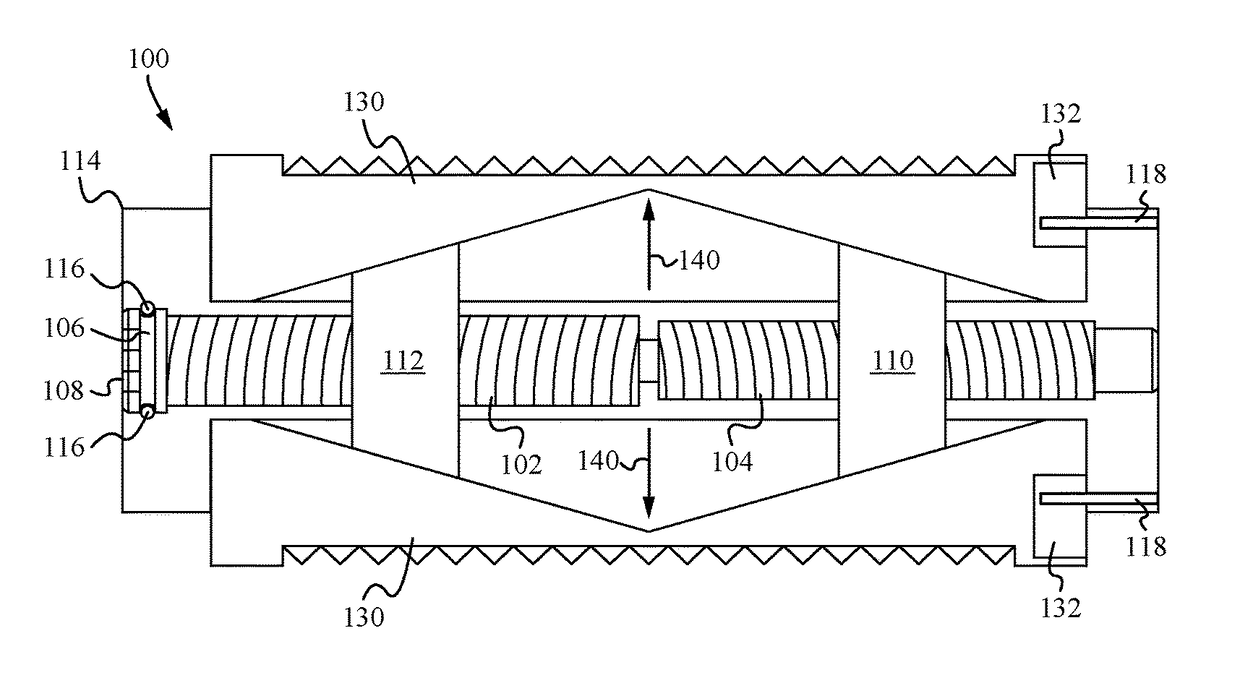
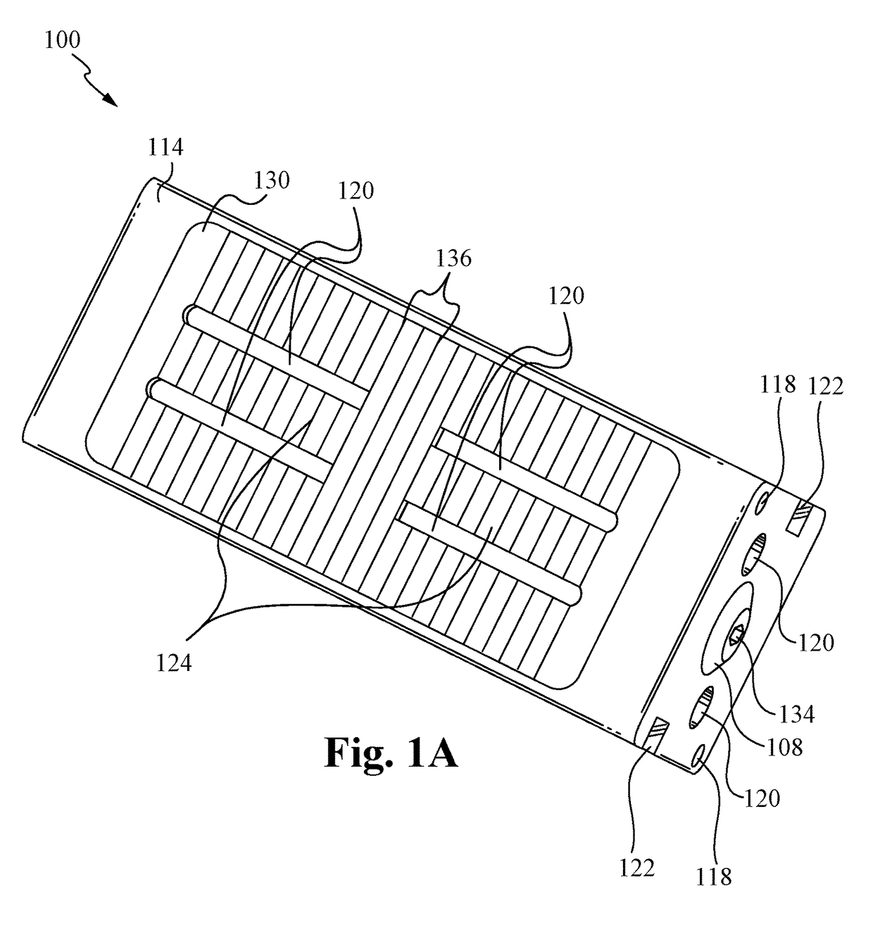
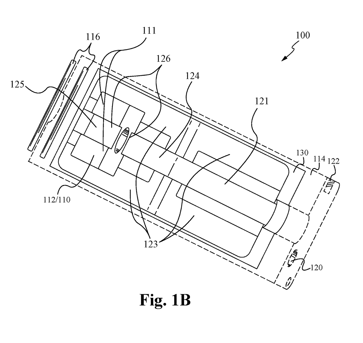
[0072]In the following description, numerous details and alternatives are set forth for purpose of explanation. However, one of ordinary skill in the art will realize that the invention can be practiced without the use of these specific details. For instance, the figures and description below often refer to the vertebral bones of a spinal column However, one of ordinary skill in the art will recognize that some embodiments of the invention are practiced for the fusion of other bones, including broken bones and / or joints. In other instances, well-known structures and devices are shown in block diagram form in order not to obscure the description of the invention with unnecessary detail. FIGS. 1A and 1B illustrate a top perspective and cutout view of the bone fusion device 100 according to some embodiments. As shown, the bone fusion device 100 has a substantially rectangular shape and has two end faces. The bone fusion device 100 is able to be constructed from a high strength biocompa...


PUM


Abstract

A bone fusion method, system and device for insertion between bones that are to be fused together in order to replace degenerated discs and/or bones, for example, the vertebrae of a spinal column The bone fusion device includes a frame and one or more extendable plates. The bone fusion device is able to be inserted between or replace the vertebrae by using a minimally invasive procedure wherein the dimensions and/or other characteristics of the bone fusion device are selectable based on the type of minimally invasive procedure.

Description

RELATED APPLICATIONS[0001]This application is a continuation-in-part of co-pending U.S. patent application Ser. No. 13 / 571,254, filed Aug. 9, 2012, and entitled “BONE FUSION DEVICE, SYSTEM AND METHOD,” which claims priority under 35 U.S.C. §119(e) of U.S. Provisional Patent Application Ser. No. 61 / 521,678, filed Aug. 9, 2011, and entitled “BONE FUSION DEVICE, SYSTEM AND METHOD,” both of which are hereby incorporated by reference.FIELD OF THE INVENTION[0002]This invention relates generally to bone fusion devices. More specifically, the present invention relates to devices for fusing vertebrae of the spine or other bones.BACKGROUND OF THE INVENTION[0003]The spinal column is made up of vertebrae stacked on top of one another. Between the vertebrae are discs which are gel-like cushions that act as shock-absorbers and keep the spine flexible. Injury, disease, or excessive pressure on the discs can cause degenerative disc disease or other disorders where the disc becomes thinner and allow...

Claims


Application Information

Patent Timeline
Patent Type & Authority Applications(United States)
IPC IPC(8): A61F2/44
CPCA61F2/447A61F2002/3093A61F2002/30904A61F2002/30579A61F2002/30527A61F2002/30418A61F2002/4687A61F2/4611A61F2002/30538A61F2/30965A61F2/442A61F2/4455A61F2/4465A61F2002/2835A61F2002/3008A61F2002/30232A61F2002/30235A61F2002/30265A61F2002/30266A61F2002/30365A61F2002/30367A61F2002/30372A61F2002/30373A61F2002/30397A61F2002/30401A61F2002/30403A61F2002/30405A61F2002/3041A61F2002/30411A61F2002/30413A61F2002/30482A61F2002/30484A61F2002/305A61F2002/30507A61F2002/30517A61F2002/3052A61F2002/30522A61F2002/30523A61F2002/30528A61F2002/30556A61F2002/30558A61F2002/30588A61F2002/30593A61F2002/30594A61F2002/30601A61F2002/30604A61F2002/30616A61F2002/30777A61F2002/30784A61F2002/30827A61F2002/30841A61F2002/30843A61F2002/4495A61F2310/00359
Inventor LOGAN, JOSEPH N.MCLUEN, GARY R.BAKER, DANIEL R.REMINGTON, BENJAMIN J.STALCUP, GREGORY C.WILLIAMS, KREIGH R.
Owner NEUROPRO TECH
Why Eureka
Try Eureka