Bi-directional fixating transvertebral body screws and posterior cervical and lumbar interarticulating joint calibrated stapling devices for spinal fusion
What is Al technical title?
Al technical title is built by PatSnap Al team. It summarizes the technical point description of the patent document.
a transvertebral body screw and lumbar interarticulation technology, applied in the field of unique universal bidirectional screw system, can solve the problems of excessive rigidity, incomplete return to work, prolonged recovery, etc., and achieve the effect of speed and safety
Active Publication Date: 2011-12-01
MOSKOWITZ FAMILY LLC
View PDF9 Cites 80 Cited by
Summary
Abstract
Description
Claims
Application Information
AI Technical Summary
This helps you quickly interpret patents by identifying the three key elements:
Problems solved by technology
Method used
Benefits of technology
[0009]We also introduce an entirely novel horizontal mini-plate capping off the intervertebral space capable of functioning as a physical barrier preventing upward bone intrusion and / or compression of the ventral thecal sac, and traversing and exciting nerve roots.
[0024]The advantage of cervical facet staples is speed and safety. The risks of cervical facet pedicle screw fixation which include nerve root and vertebral artery injuries are completely obviated. Thus they thereby achieve the same function of pedicle screws without the risks.
Problems solved by technology
Complications of pedicle screw placement in cervical, thoracic and lumbar spine include duration of procedure, significant tissue dissection and muscle retraction, misplaced screws with neural and / or vascular injury, excessive blood loss, need for transfusions, prolonged recovery, incomplete return to work, and excess rigidity leading to adjacent segmental disease requiring further fusions and re-operations.
Complications of all current spinal interbody fusion devices is their lack of coverage of the majority of the cross-sectional area of the vertebral endplates, and their lack of adequate, if any capacity to penetrate bone, and hence the heightened risk of implant extrusion.
Method used
Image
Click on the blue label to locate the original text in one second.
Reading with bidirectional positioning of images and text.
Examples
Embodiment Construction
[0062]1. The Medical Device
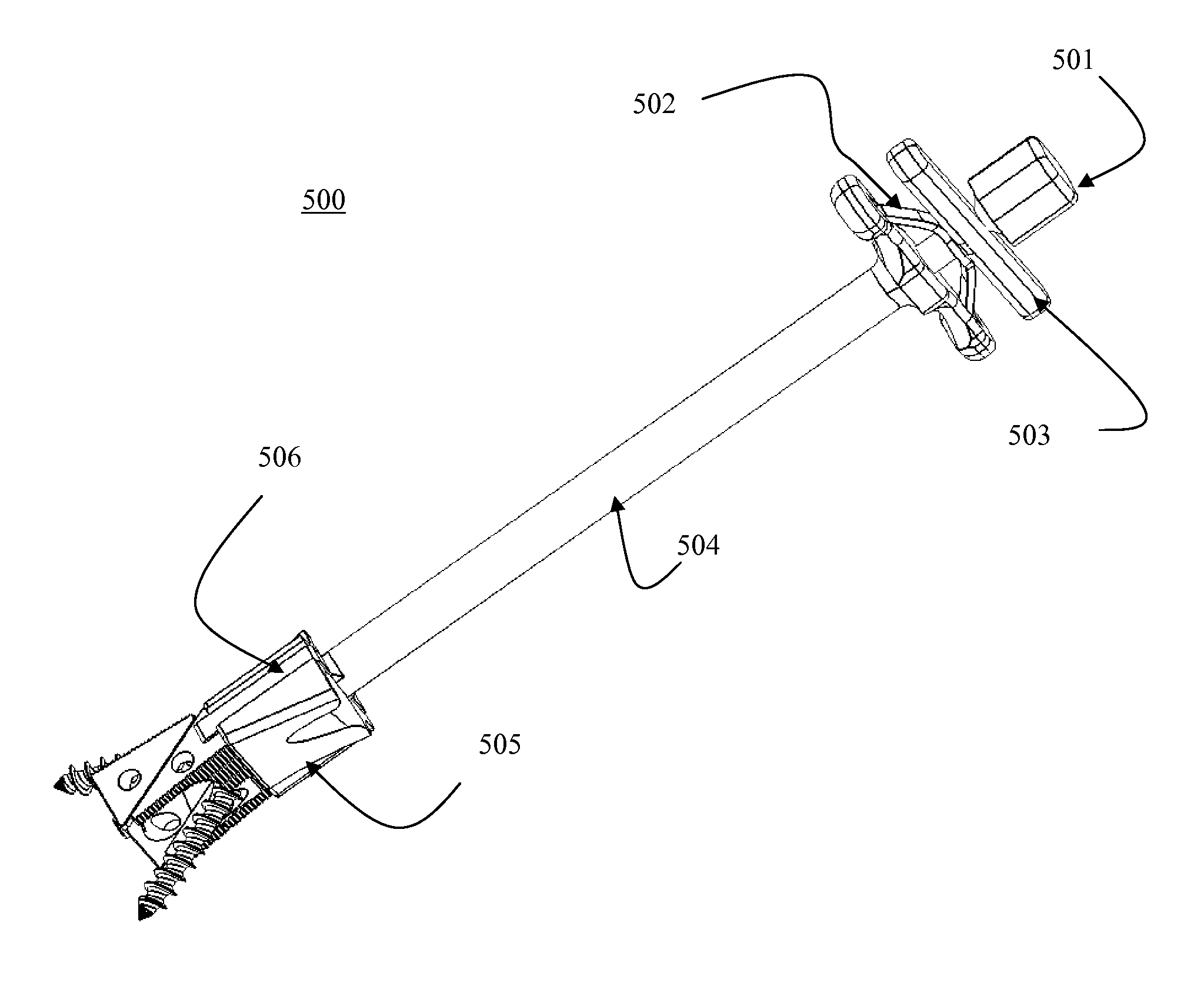
[0063]Referring to FIGS. 1-6, the above described problem can be solved in the thoracic and lumbar spine by insertion into the denuded intervertebral disc space multiple embodiments of screw box constructs with BDFT screws.
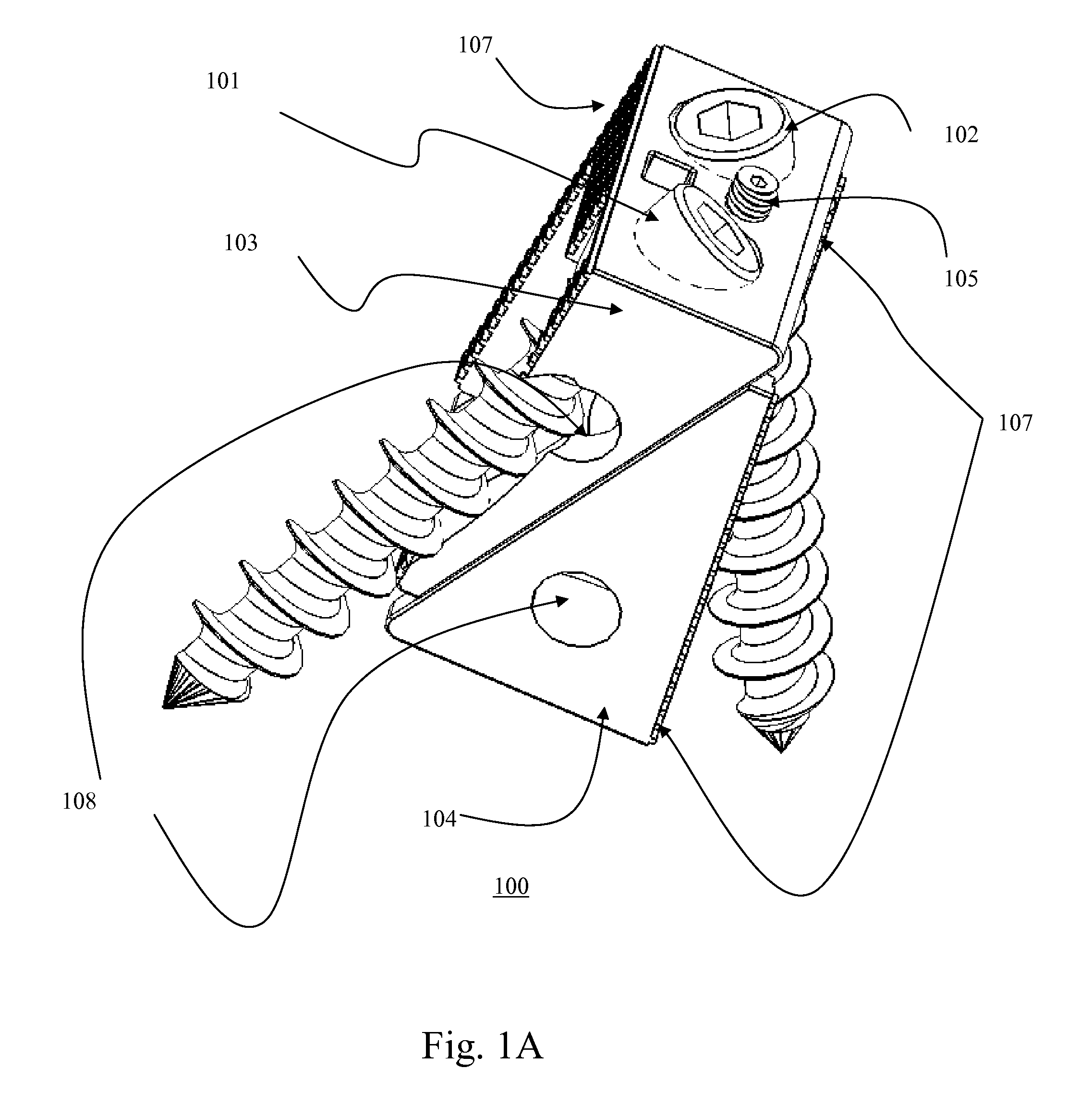
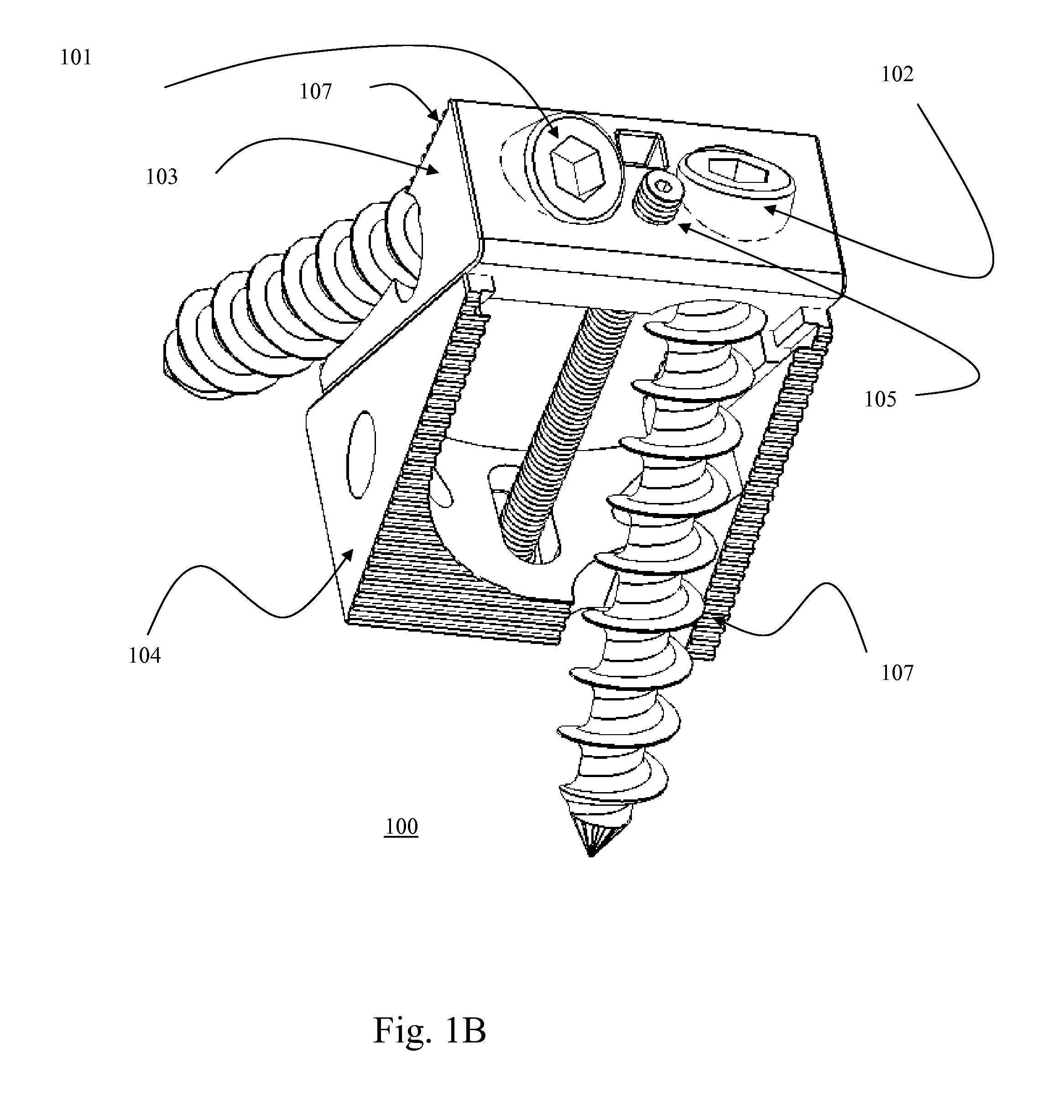
[0064]FIGS. 1A-D illustrate three-dimensional views of the Lumbar intervertebral expandable screw box 100 with two BDFT screws 101, 102; one lateral and one medially oriented (Embodiment IA). FIG. 1E illustrates a sagittal-oblique view of the lumbar intervertebral expandable screw box 120 with two lateral oriented BDFT screws 121, 122 (Embodiment IB).
[0065]The expandable box 100 consists of top and bottom triangular sliding bases 103, 104 (FIG. 1-D). The superior and inferior segments of the height / depth adjusting screw 105 are integrated and connected to the two separate top and bottom triangular bases 103, 104, respectively. By turning this adjusting screw 105 back and forth i.e. clock-wise, and counter clockwise, the sliding rails 106...
PUM
Abstract
A self-drilling bone fusion screw apparatus is disclosed which includes at least first and second sliding boxes. A first screw member having a tapered end and a threaded body is disposed within the first sliding box, and a second screw member having a tapered end and a threaded body disposed within the second sliding box. An adjuster adjusts the height of the sliding boxes. The screw members are screwed into vertebral bodies in order to fuse the vertebral bodies together. A plurality of the self-drilling bone fusion screw apparatuses may be attached together and / or integrated via a plate or cage. Also disclosed is a cervical facet staple that includes a curved staple base and at least two prongs attached to the bottom surface of the curved staple base.
Description
CROSS-REFERENCE TO RELATED APPLICATIONS[0001]This application is a Continuation Application of application Ser. No. 11 / 842,855, filed on Aug. 21, 2007, now U.S. Pat. No. 7,942,903 issued on May 17, 2011, which is a Continuation-In-Part Application of application Ser. No. 11 / 536,815, filed on Sep. 29, 2006, now U.S. Pat. No. 7,846,188 issued on Dec. 7, 2010, which is a Continuation-In-Part Application of application Ser. No. 11 / 208,644, filed on Aug. 23, 2005, now U.S. Pat. No. 7,704,279 issued on Apr. 27, 2010, for which priority is claimed under 35 U.S.C. §120; and this application also claims priority under 35 U.S.C. §119(e) of U.S. provisional application No. 60 / 670,231, filed on Apr. 12, 2005; the entire contents of all the above identified patent applications are hereby incorporated by reference.BACKGROUND OF THE INVENTION[0002]1. Field of Invention[0003]The present invention relates to a unique universal bidirectional screw (BDS) system, and in particular its application to th...
Claims
Application Information
Patent Timeline
Application Date:The date an application was filed.
Publication Date:The date a patent or application was officially published.
First Publication Date:The earliest publication date of a patent with the same application number.
Issue Date:Publication date of the patent grant document.
PCT Entry Date:The Entry date of PCT National Phase.
Estimated Expiry Date:The statutory expiry date of a patent right according to the Patent Law, and it is the longest term of protection that the patent right can achieve without the termination of the patent right due to other reasons(Term extension factor has been taken into account ).
Invalid Date:Actual expiry date is based on effective date or publication date of legal transaction data of invalid patent.
Patent Type & Authority Applications(United States)