Bi-directional fixating transvertebral body screws and posterior cervical and lumbar interarticulating joint calibrated stapling devices for spinal fusion

a transvertebral body screw and lumbar interarticulation joint technology, applied in the field of unique universal bidirectional screw system, can solve the problems of excessive rigidity, incomplete return to work, prolonged recovery, etc., and achieve the effect of less nerve root retraction, less screw box width and small width

Active Publication Date: 2008-02-07
MOSKOWITZ FAMILY LLC
View PDF49 Cites 295 Cited by
  • Summary
  • Abstract
  • Description
  • Claims
  • Application Information

AI Technical Summary

Benefits of technology

[0012] In yet another embodiment we designed a screw box which houses only one, instead of two screws. Each box allows the placement of one superior or inferior directed screw on one side (left or right), and the contra lateral screw box device allows placement of an inferior or superior oriented screw which goes in the opposite direction of the contra lateral device. In totality these two separate single screw boxes fuse the superior and inferior vertebrae. The potential advantage of this embodiment is that it diminishes the width of the screw box in cases where it might be favorable to have less nerve root retraction with a smaller width device.
[0013] In all screw-box embodiments, a rostral-directed screw is passed through one built-in screw guide of the device which then is inserted and screwed into the superior vertebral body. Then a caudaly directed screw is passed through an adjacent built-in screw guide which then is inserted and screwed into the inferior vertebral body. The novelty of this design is the built-in prescribed angles of the integral screw guides which allow the posterior transvertebral penetration into the vertebral bodies. This is a truly amazing feat accomplished in the posterior lumbar spine considering the small anatomically restricted work zone within which to work, which is very narrowly prescribed by obtuse angulations between screw and intervertebral bone surfaces, and by nerve root, facet joint and pedicle. We have also designed a positioning tool for the placement of the non-expandable screw boxes which has a screwdriver with a flexible shaft specifically designed to fit these devices if a straight screw driver impedes screw placement. Hence these external tools provide the means in any circumstance to accomplish precision screw trajectory. The embodiments described herein compared to our previous co-pending patent designs, streamline and ease production of bi-directionally oriented transvertebral screws, and allows placement of longer and wider screws with greater bone penetration to provide yet a sturdier fusion construct. The designs are also easily modifiable for anterior placement into the cervical spine. The expandable embodiment of the screw box can also be enlarged and modified to be suitable for cervical, thoracic and lumber vertebral body replacements.
[0014] The box casings have multiple perforations to allow both screw traversal and horizontal bone packing preventing upward vertical migration of bone. The boxes prevent subsidence. Both the inside of the denuded intervertebral space, and the screw boxes can be packed with autologous or allograft bone, BMP, DBX or similar osteoconductive material. Posteriorly or anteriorly in the lumbar
[0015] It is believed that BDFT-screw constructs provide as strong or stronger segmental fusion as pedicle screws without the complications arising from pedicle screw placement which include screw misplacement with potential nerve and / or vascular injury, violation of healthy facets, possible pedicle destruction, blood loss, and overly rigid fusions. By placing screws across the intervertebral space from vertebral body to vertebral body, engaging anterior and middle spinal columns, and not the vertebral bodies via the transpediclar route, the healthy facet joints, if they exist, are preserved. Because this technique accomplishes both anterior and middle column fusion, without rigidly fixating the posterior column, it in essence creates a flexible fusion. This device therefore is a flexible fusion device because the preserved posterior facet joints retain their function achieving at least a modicum of mobility and hence a less rigid (i.e. a flexible) fusion.
[0016] The very advantage of transpedicular screws which facilitate a strong solid fusion by rigidly engaging all three spinal columns is the same mechanical mechanism whereby complete inflexibility of all columns is incurred thereby leading to increasing rostral and caudal segmental stress which leads to an increased rate of re-operation.
[0017] Transvertebral fusion also leads to far less muscle retraction, blood loss, and significant reduction in O.R. time. Thus the complication of pedicular screw pull-out and hence high re-operation rate associated with the current embodiment of flexible fusion pedicle screws / rods is obviated. The lumbosacral screw box embodiments and BDFT screws can be introduced via posterior lateral, transforaminal or anterior interbody fusion approaches / techniques. Although one can opt to supplement these screws with transpedicular screws there would be no absolute need for supplemental pedicle screw fixation with these operative techniques.

Problems solved by technology

Complications of pedicle screw placement in cervical, thoracic and lumbar spine include duration of procedure, significant tissue dissection and muscle retraction, misplaced screws with neural and / or vascular injury, excessive blood loss, need for transfusions, prolonged recovery, incomplete return to work, and excess rigidity leading to adjacent segmental disease requiring further fusions and re-operations.
Complications of all current spinal interbody fusion devices is their lack of coverage of the majority of the cross-sectional area of the vertebral endplates, and their lack of adequate, if any capacity to penetrate bone, and hence the heightened risk of implant extrusion.

Method used


Image

  • Bi-directional fixating transvertebral body screws and posterior cervical and lumbar interarticulating joint calibrated stapling devices for spinal fusion
  • Bi-directional fixating transvertebral body screws and posterior cervical and lumbar interarticulating joint calibrated stapling devices for spinal fusion
  • Bi-directional fixating transvertebral body screws and posterior cervical and lumbar interarticulating joint calibrated stapling devices for spinal fusion

Examples


Embodiment Construction

[0060] 1. The Medical Device

[0061] Referring to FIGS. 1-6, the above described problem can be solved in the thoracic and lumbar spine by insertion into the denuded intervertebral disc space multiple embodiments of screw box constructs with BDFT screws.

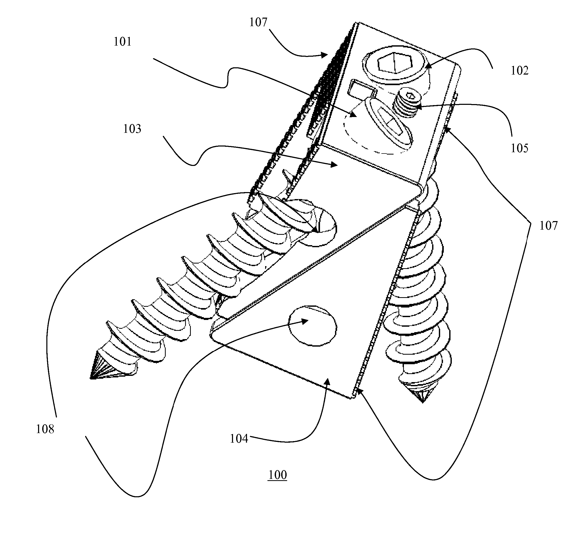
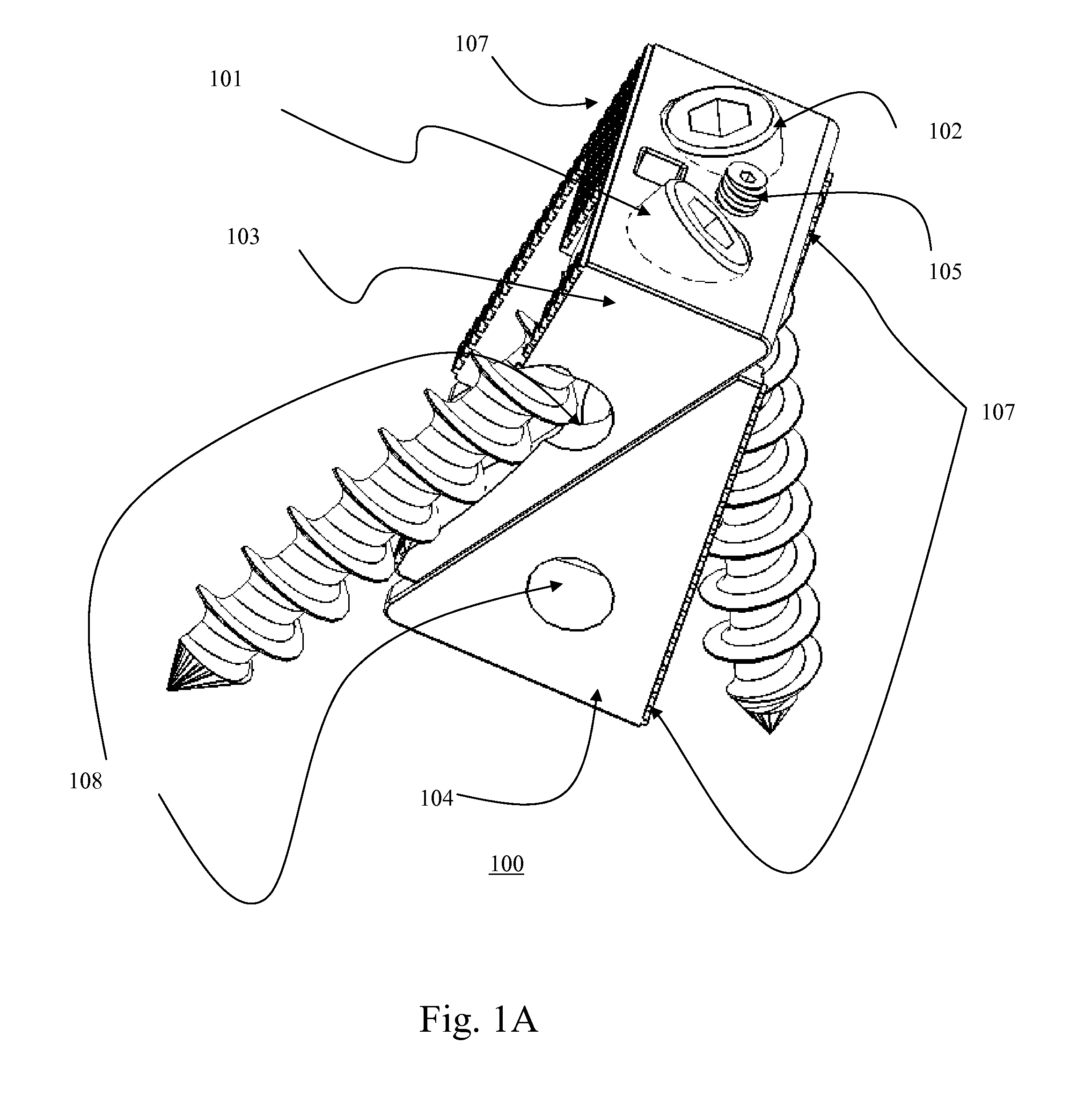
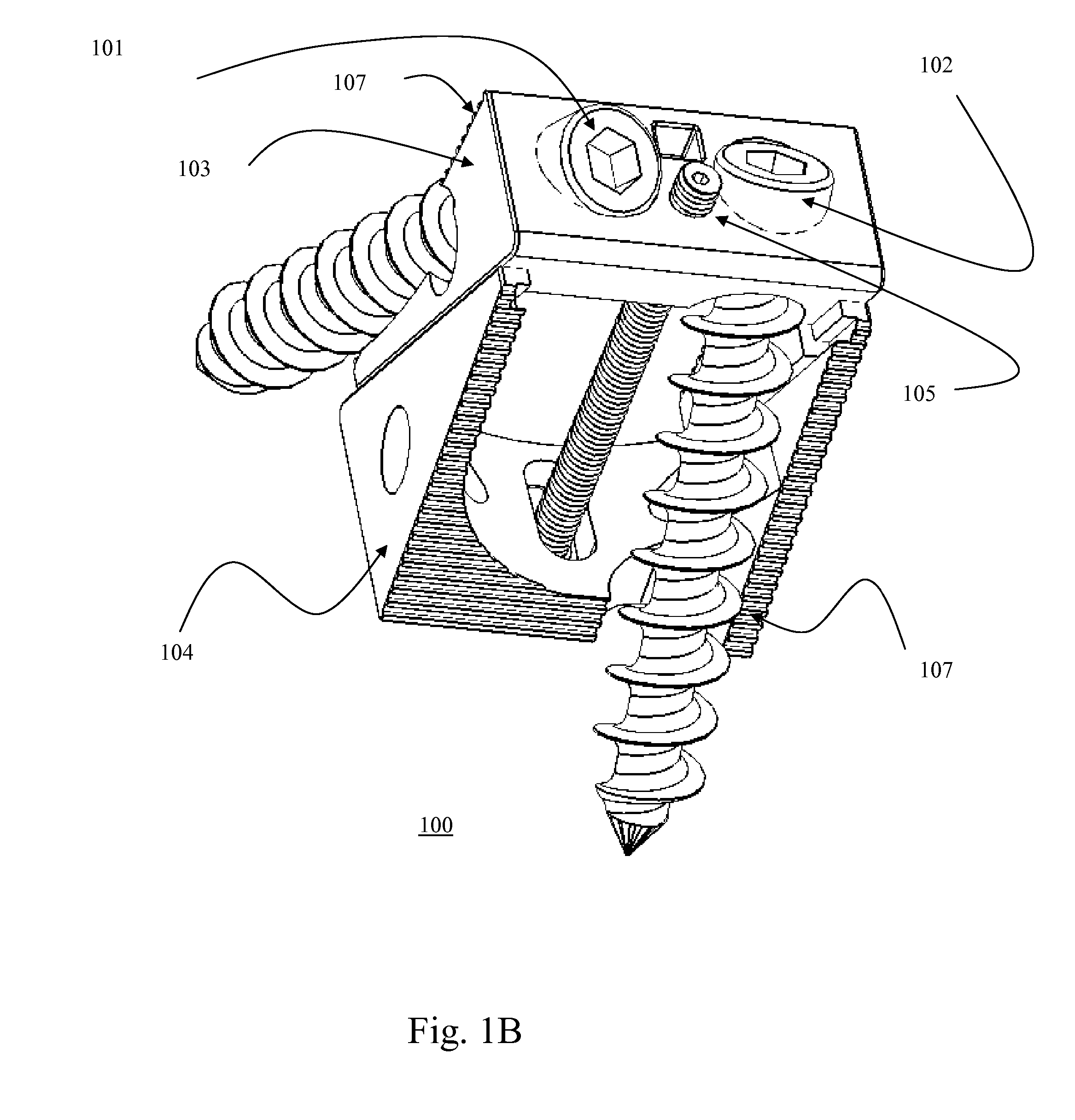
[0062] FIGS. 1A-D illustrate three-dimensional views of the Lumbar intervertebral expandable screw box 100 with two BDFT screws 101, 102; one lateral and one medially oriented (Embodiment IA). FIG. 1E illustrates a sagittal-oblique view of the lumbar intervertebral expandable screw box 120 with two lateral oriented BDFT screws 121, 122 (Embodiment IB).

[0063] The expandable box 100 consists of top and bottom triangular sliding bases 103, 104 (FIG. 1-D). The superior and inferior segments of the height / depth adjusting screw 105 are integrated and connected to the two separate top and bottom triangular bases 103, 104, respectively. By turning this adjusting screw 105 back and forth i.e. clock-wise, and counter clockwise, the sliding ra...


PUM


Abstract

A self-drilling bone fusion screw apparatus is disclosed which includes at least first and second sliding boxes. A first screw member having a tapered end and a threaded body is disposed within the first sliding box, and a second screw member having a tapered end and a threaded body disposed within the second sliding box. An adjuster adjusts the height of the sliding boxes. The screw members are screwed into vertebral bodies in order to fuse the vertebral bodies together. A plurality of the self-drilling bone fusion screw apparatuses may be attached together and/or integrated via a plate or cage. Also disclosed is a cervical facet staple that includes a curved staple base and at least two prongs attached to the bottom surface of the curved staple base.

Description

[0001] This application is a Continuation-In-Part Application of copending application Ser. No. 11 / 536,815, filed on Sep. 29, 2006, which is a Continuation-In-Part Application of copending application Ser. No. 11 / 208,644, filed on Aug. 23, 2005 for which priority is claimed under 35, U.S.C. §120; and this application also claims priority under 35 U.S.C. § 119(e) of U.S. provisional application No. 60 / 670,231, filed on Apr. 12, 2005; the entire contents of all the above identified patent applications are hereby incorporated by reference.FIELD OF INVENTION [0002] The present invention relates to a unique universal bidirectional screw (BDS) system, and in particular its application to the spine, also referred to as bi-directional fixating transvertebral (BDFT) screws which can be used as a stand-alone intervertebral device which combines the dual functions of an intervertebral spacer which can be filled with bone fusion material(s), as well as a transvertebral bone fusion screw apparat...

Claims


Application Information

Patent Timeline
Patent Type & Authority Applications(United States)
IPC IPC(8): A61B17/58
CPCA61B17/0642A61F2002/4687A61B17/809A61B17/86A61B17/8894A61B2017/0641A61B2017/0648A61B2017/922A61F2/4465A61F2/447A61F2/4611A61F2002/2835A61F2002/30133A61F2002/30387A61F2002/30448A61F2002/30507A61F2002/3055A61F2002/30579A61F2002/30604A61F2002/30772A61F2002/30878A61F2002/4475A61F2002/448A61F2002/4627A61F2002/4681A61F2220/0025A61F2220/005A61F2230/0015A61F2250/0007A61B17/7064A61B2017/00407A61B17/0644A61B17/1757A61B17/8875A61F2002/30879A61F2002/30904A61F2002/30593A61B17/8635A61B17/92
Inventor MOSKOWITZ, AHMNON D.ALVARADO, PABLO A. VALDIVIA Y.MOSKOWITZ, MOSHEH T.MOSKOWITZ, NATHAN C.
Owner MOSKOWITZ FAMILY LLC
Why Eureka
Try Eureka