Methods for fabricating fin field effect transistors using a protective layer to reduce etching damage

a field effect transistor and protective layer technology, applied in the field of field effect transistors, can solve problems such as increased parasitic capacitance between junction regions, increased leakage current, and possible problems associated with transistor characteristics degradation

Active Publication Date: 2006-07-11
SAMSUNG ELECTRONICS CO LTD
View PDF6 Cites 179 Cited by
  • Summary
  • Abstract
  • Description
  • Claims
  • Application Information

AI Technical Summary

Benefits of technology

[0020]In some embodiments, the dummy gate may be formed by oxidizing a portion of the dummy gate and then removing the oxidized portion of the dummy gate to reduce a width of the dummy gate.

Problems solved by technology

As semiconductor devices become highly integrated, problems associated with degradation of transistor characteristics may arise.
Examples of these problems may include short channel effects such as punch-through, Drain Induced Barrier Lowering (DIBL), and subthreshold swing, as well as increased parasitic capacitance between the junction region and the substrate (i.e. a junction capacitor) and increased leakage current.
However, the sidewalls of silicon fins (i.e. the channel region) may be damaged by the etching process.
For example, the thickness of the gate oxide layer may become thin at the edge of the gate due to over-etching, such that gate induced diode leakage (GIDL) may occur.

Method used


Image

  • Methods for fabricating fin field effect transistors using a protective layer to reduce etching damage
  • Methods for fabricating fin field effect transistors using a protective layer to reduce etching damage
  • Methods for fabricating fin field effect transistors using a protective layer to reduce etching damage

Examples


Embodiment Construction

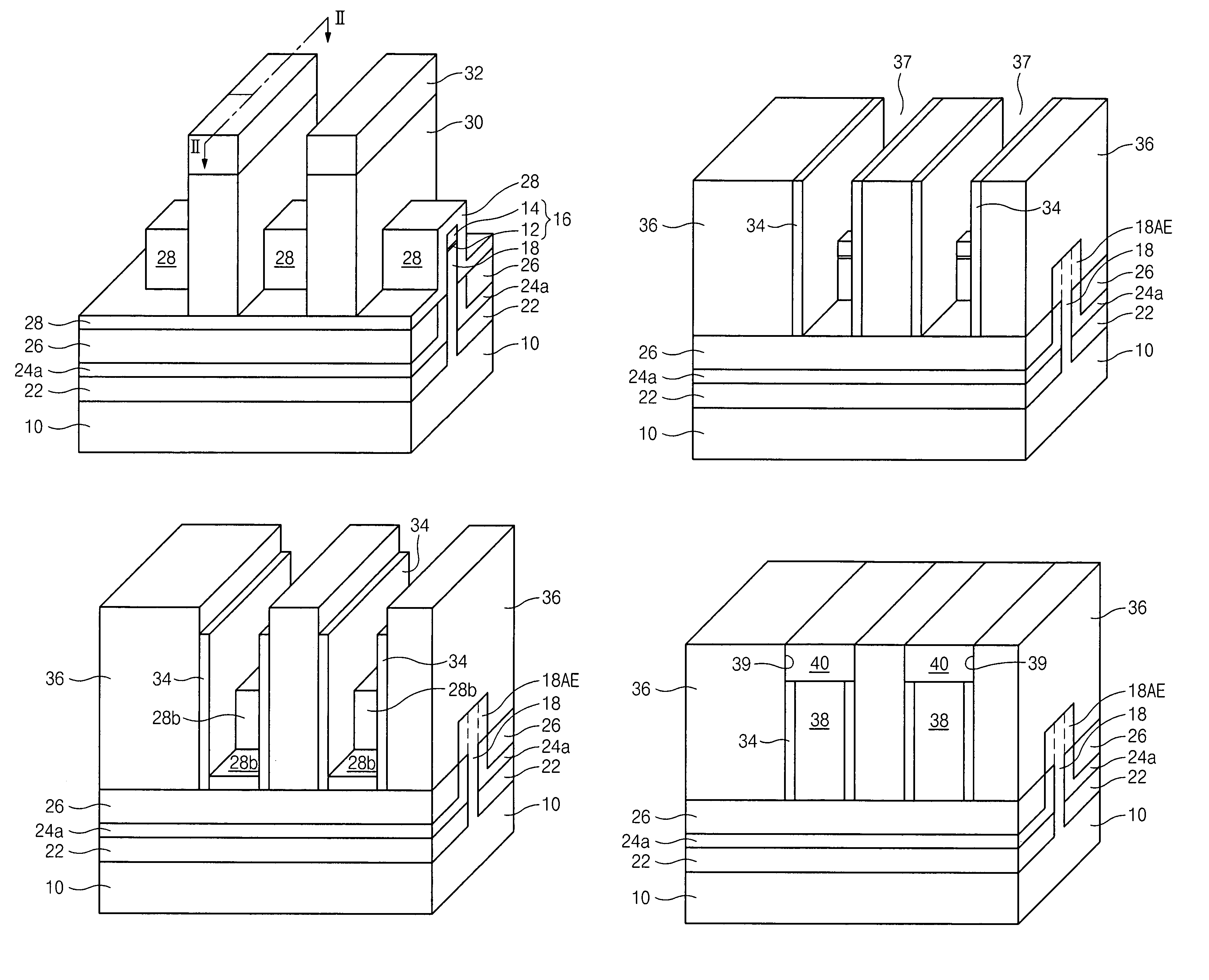
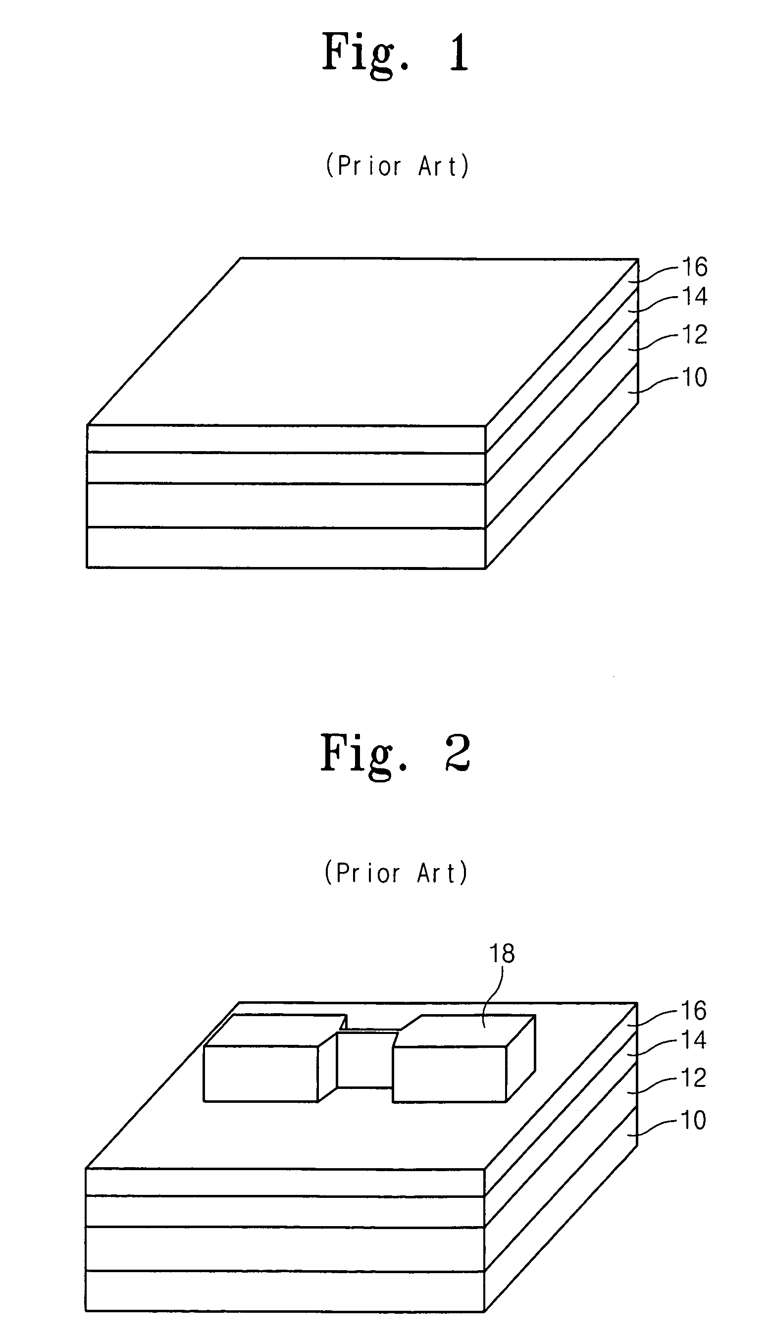
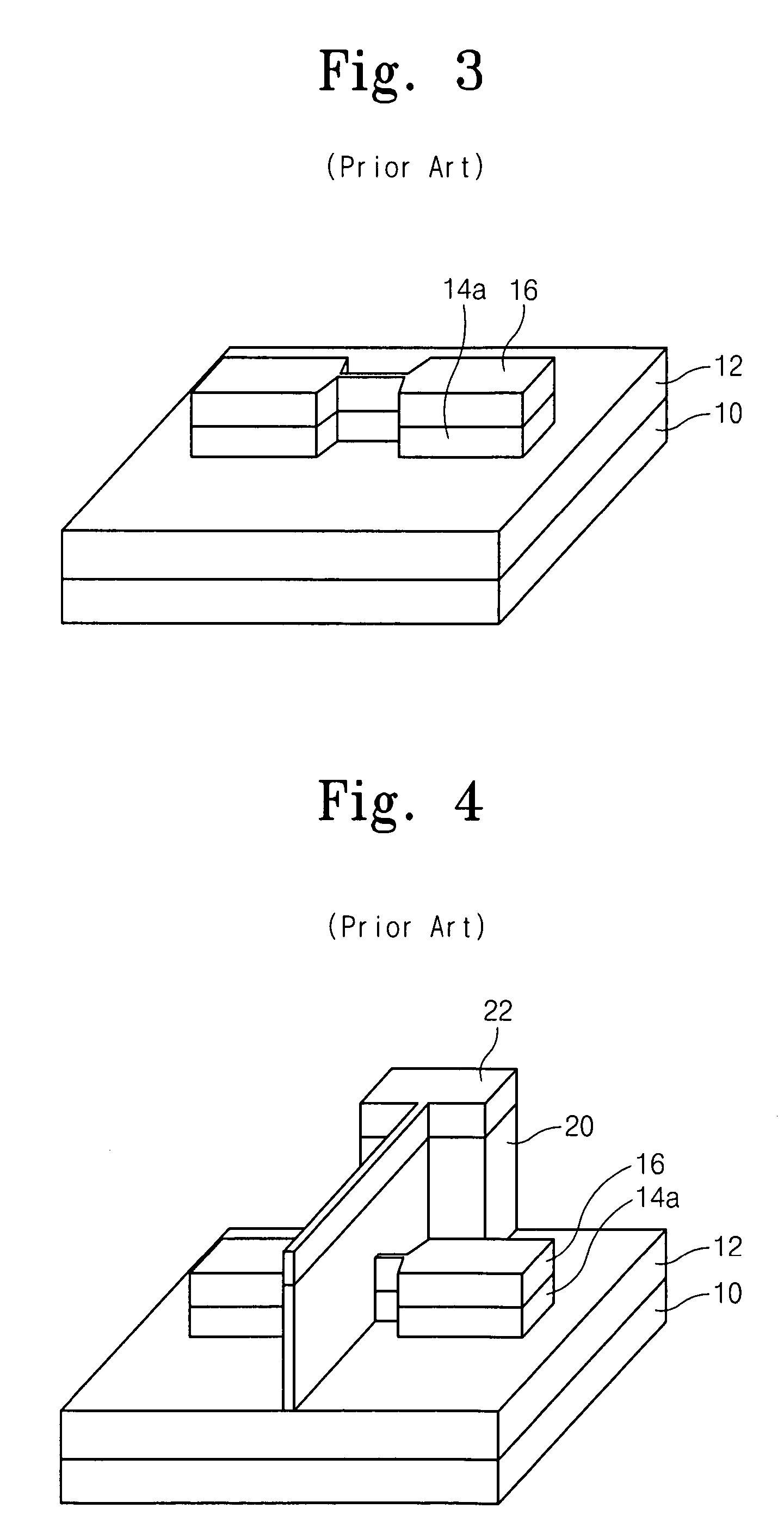
[0030]The present invention now will be described more fully hereinafter with reference to the accompanying drawings, in which preferred embodiments of the invention are shown. This invention may, however, be embodied in many different forms and should not be construed as limited to the embodiments set forth herein; rather, these embodiments are provided so that this disclosure will be thorough and complete, and will fully convey the scope of the invention to those skilled in the art. In the drawings, the thickness of layers and regions are exaggerated for clarity. It will be understood that when an element such as a layer, region or substrate is referred to as being “on” another element, it can be directly on the other element or intervening elements may also be present. It will be understood that when an element such as a layer, region or substrate is referred to as “under” another element, it can be directly under the other element or intervening elements may also be present. It ...


PUM


Abstract

A method of forming a fin field effect transistor on a semiconductor substrate includes forming a vertical fin protruding from the substrate. A buffer oxide liner is formed on a top surface and on sidewalls of the fin. A trench is then formed on the substrate, where at least a portion of the fin protrudes from a bottom surface of the trench. The trench may be formed by forming a dummy gate on at least a portion of the fin, forming an insulation layer on the fin surrounding the dummy gate, and then removing the dummy gate to expose the at least a portion of the fin, such that the trench is surrounded by the insulation layer. The buffer oxide liner is then removed from the protruding portion of the fin, and a gate is formed in the trench on the protruding portion of the fin.

Description

CLAIM OF PRIORITY[0001]This application claims priority from Korean Patent Application No. 10-2003-51028, filed on Jul. 24, 2003, the disclosure of which is hereby incorporated herein by reference.BACKGROUND OF THE INVENTION[0002]1. Field of the Invention[0003]The present invention relates to semiconductor devices, and, more particularly, to Field-Effect Transistors (FETs) and methods of fabricating the same.[0004]2. Description of the Related Art[0005]As semiconductor devices become highly integrated, problems associated with degradation of transistor characteristics may arise. Examples of these problems may include short channel effects such as punch-through, Drain Induced Barrier Lowering (DIBL), and subthreshold swing, as well as increased parasitic capacitance between the junction region and the substrate (i.e. a junction capacitor) and increased leakage current.[0006]Double-gate field-effect transistors may overcome many of these problems. In a double-gate field-effect transis...

Claims


Application Information

Patent Timeline
Patent Type & Authority Patents(United States)
IPC IPC(8): H01L21/8238H01L21/336H01L21/84H01L27/12H01L29/423H01L29/786
CPCH01L21/84H01L27/1203H01L29/7851H01L29/66795H01L29/42384H01L29/66545H01L21/845H01L27/1211H01L21/18
Inventor LEE, DEOK-HYUNGCHOI, SI-YOUNGLEE, BYEONG-CHANSON, YONG-HOONJUNG, IN-SOO
Owner SAMSUNG ELECTRONICS CO LTD
Why Eureka
Try Eureka