Distal interphalangeal fusion method and device

a technology of distal interphalangeal fusion and joint fusion, which is applied in the field of medical devices and medical procedures, can solve the problems of inability to achieve esthetically pleasing, weaken grip strength, and extreme pain of joint disorders such as arthritis in the joints of digits, and achieve the effect of facilitating the coordination of screw threads

Inactive Publication Date: 2013-09-10
COMPETITIVE GLOBAL MEDICAL
View PDF57 Cites 80 Cited by
  • Summary
  • Abstract
  • Description
  • Claims
  • Application Information

AI Technical Summary

Benefits of technology

[0010]An embodiment of a method of maintaining thread synchronization of a bone fusion apparatus having a discontinuous thread is provided, the apparatus having a first screw thread on a leading component and a second screw thread on a trailing component, the two components being separated by a coupling non-threaded component, the separate screw threads having the same thread pitch, comprising providing at least two driving patterns in the trailing and non-threaded component to coordinate the separate screw threads with each other such that a single driving tool having the at least two complementary driving patterns will facilitate coordination of the screw threads by synchronized alignment and rotation of the trailing and non-threaded components.

Problems solved by technology

Joint disorders, such as arthritis in the joints of digits, can be extremely painful.
This fully-extended orientation of the digit in conventional arthrodesis techniques weakens grip strength and is often not esthetically pleasing to the patient.
If a finger is extended, it cannot properly oppose the other fingers to grasp the object, stabilize the object in the hand, or exert force on the object.
Moreover, the digits of a human hand rest in a flexed position; therefore, a digit that is fused in an extended position looks abnormal and is not esthetically pleasing.
Similarly, straight toe joints are unnatural and do not grip or fit properly within normal shoes.
One complication arising from the arthrodesis surgery is misalignment, or crooked, fusion at the joint.
This can arise from imperfect alignment of the bone ends during surgery, subsequent misalignments caused by lateral impact during the healing process, or in the case of arthrodesis utilizing an implanted bone screw having a flexible joint, lateral rotation about the joint during healing.

Method used


Image

  • Distal interphalangeal fusion method and device
  • Distal interphalangeal fusion method and device
  • Distal interphalangeal fusion method and device

Examples


example 1

Cannulated Flexible Three-Part DIP Fusion Apparatus

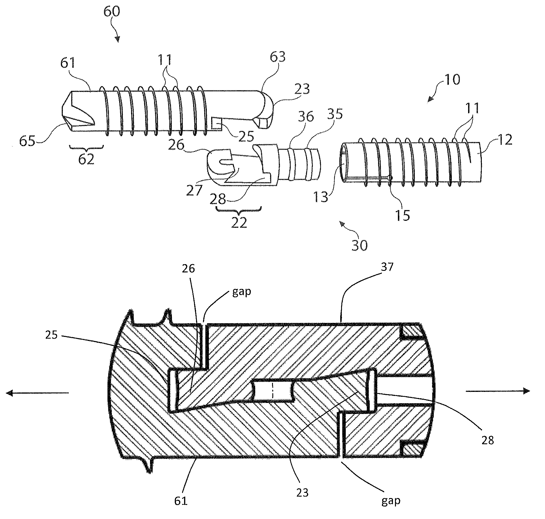
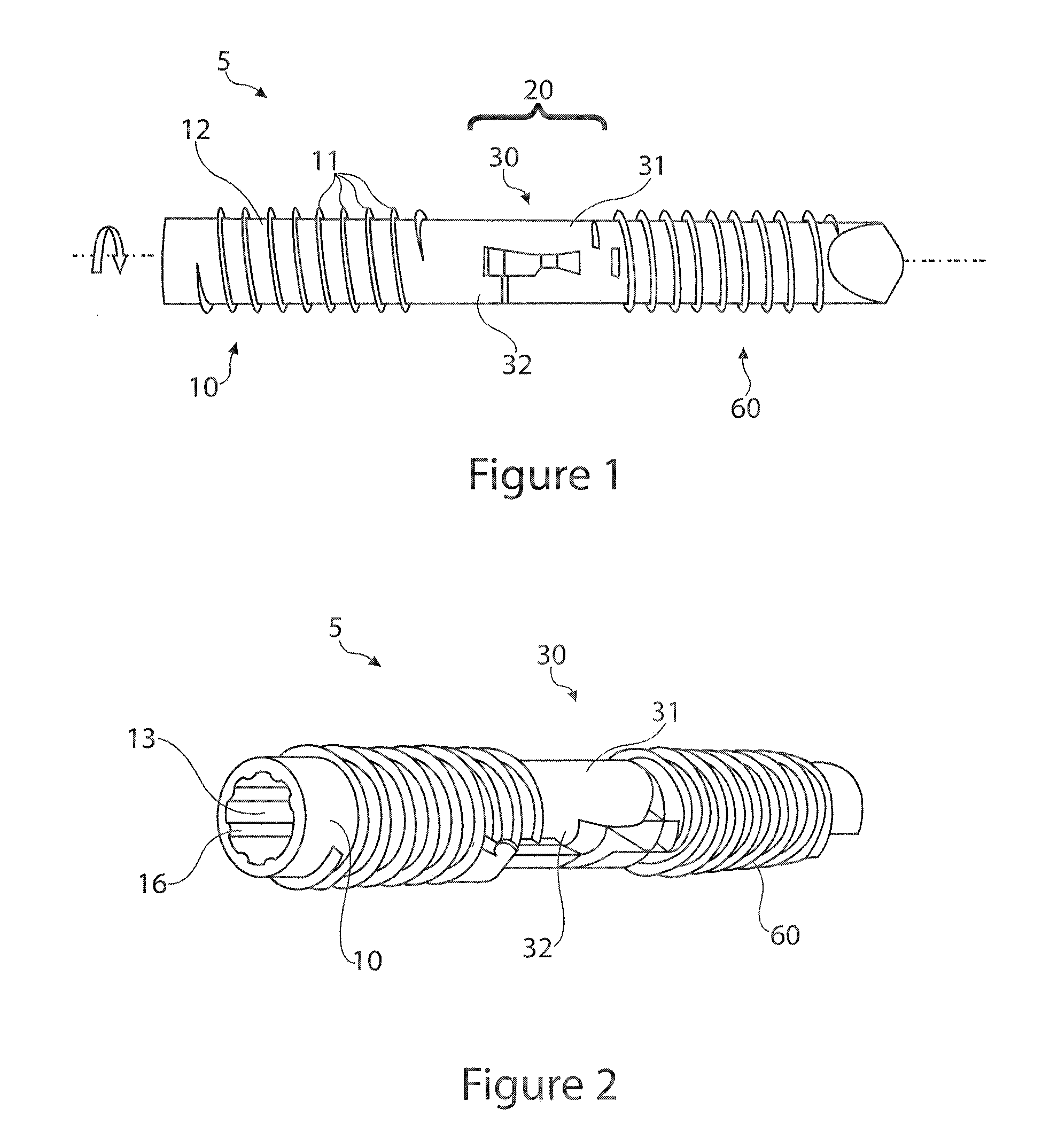
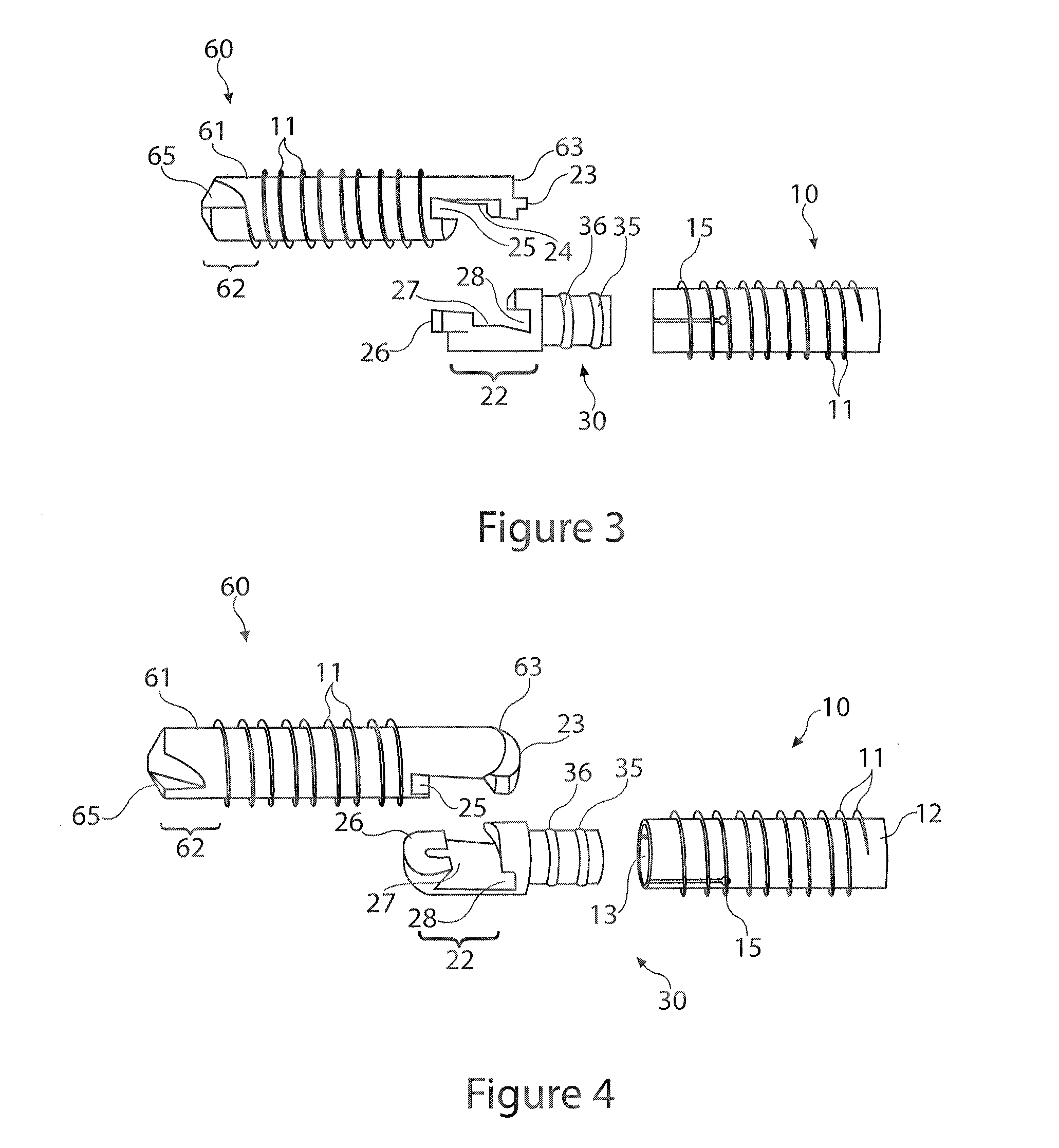
[0077]FIGS. 1-16, 32-33 disclose a first embodiment of the invention which may or may not be designed to be installed over a K-wire. The flexible bone fusion apparatus 5 of FIG. 1 comprises three main components, a compressor portion 10, coupler portion 30 and anchor portion 60. The coupler portion imparts overall flexibility to the design and allows the bone fusion apparatus to flex in a single plane at a DIP joint to emulate a natural curvature of the joint (e.g., finger or toe) post-fusion. FIG. 1 depicts all three components together in their unlocked assembled arrangement. When installing the device in bones such as either the finger or toe a cannulated delivery tool 100 (FIGS. 17-19) is inserted into the end of the assembled flexible bone fusion device 5. The delivery tool resembles a screwdriver in that it has a handle and shaft, but this tool is specially adapted to engage the compressor lumen of the bone fusion device throu...

example 2

Non-Cannulated Flexible Three-Part DIP Fusion Apparatus

[0101]Another embodiment of the DIP fusion apparatus employs an anchor portion 60 that does not have a cannula that opens to the leading tip and so would not be used with a K-wire. However, a cannula may be utilized through the anchor attachment portion 21. No separate figure shows this embodiment since to remove the opening is adequately disclosed by description only. With respect to FIGS. 5-8, in this alternate embodiment the anchor lumen / cannula 64 in anchor locking wedge 23, anchor axial face 24 and continuing through the anchor annular groove 25 would still exist. The delivery tool alignment pin 105 would engage the anchor as before, via coupler and through at least the anchor locking wedge part of the attachment assembly 20 (FIG. 1). With reference to FIG. 7, the tip hole 66 shown in the anchor leading tip 62 would not be present in this embodiment.

[0102]Compressor tool 110 shown in FIGS. 23-24 is a non-cannulated delivery...

example 3

Linear Two-Part Bone Fusion Apparatus

[0103]Another embodiment of the inventive concept disclosed herein is described and disclosed in FIGS. 28-31. In this embodiment the bone fusion apparatus does not flex about the coupler as the coupler's flex feature has been removed. Instead the apparatus comprises two components, an anchor portion and a compressor portion. This embodiment still accomplishes compression and fusion of two fractured parts or adjacent bones, although it has not been designed to flex about its longitudinal axis (long axis). The anchor portion is very similar to the anchor portion of the first example, although the trailing end has been modified to directly couple to the compressor portion. The compressor remains the same as the embodiments described in Example 1. Description of this embodiment is largely restricted to just those features that differ from the embodiments of Example 1, unless otherwise noted. If a feature is not noted in this example but it is visible...


PUM


Abstract

A system, including methods, apparatus and kits for connecting bones and / or bone portions using a multi-part bone connector with one or more rotating joints is disclosed. A flexible bone fusion apparatus is provided having an anchor and a compressor, each of which engages with a coupler to provide axial and / or linear rotation of the apparatus. Alternatively, a compressor and an anchor may directly join with each other at a shared interface. Tools for installing and compressing the apparatus are provided. Also provided is a method for fusing two bones or bone portions to create a non-linear post-fusion orientation. A further aspect of the disclosure is a method for maintaining thread synchronization of a bone fusion apparatus having a discontinuous thread.

Description

CROSS REFERENCE TO RELATED APPLICATIONS[0001]This application claims priority to U.S. Provisional Application No. 61 / 314,317, filed Mar. 16, 2010, the contents of which are incorporated by reference herein in their entirety.BACKGROUND[0002]The embodiments of the invention disclosed herein generally relate to a medical device and medical procedure using that device, and more particularly, to a joint fusion assembly for arthroplastic convergence of opposing ends of bones.[0003]Joint disorders, such as arthritis in the joints of digits, can be extremely painful. A common procedure to alleviate pain in such patients is to fixate the joint for fusion by arthrodesis. There are a number of arthrodesis techniques that promote fusion of adjacent bones of a digit (e.g., finger or toe). Historically, these techniques utilize a bone screw that draws the adjacent bones together at a 180 degree, or straight, angle. The digit then fuses at the joint in a fully-extended orientation. This fully-exte...

Claims


Application Information

Patent Timeline
Patent Type & Authority Patents(United States)
IPC IPC(8): A61B17/84A61B17/86
CPCA61B17/7225A61B17/84A61B17/7258A61B17/7291A61F2/4225A61F2/4241A61B17/7233A61B17/8625A61B17/8685A61F2/4606A61F2002/30622A61F2002/3085A61F2002/4228A61F2002/4243A61F2002/4246A61F2002/4677
Inventor CHAMPAGNE, LLOYDKING, BRUCECONTENTO, OMARLANHAM, MIKEMARTIN, DONALD J.
Owner COMPETITIVE GLOBAL MEDICAL
Why Eureka
Try Eureka