Fuel injection valve

a fuel injection valve and valve needle technology, applied in the direction of valve operating means/release devices, machines/engines, mechanical equipment, etc., can solve the problems of short-term opening of the fuel injector, opening stroke of the valve needle, and magnetic for

Inactive Publication Date: 2003-01-28
ROBERT BOSCH GMBH
View PDF11 Cites 69 Cited by
  • Summary
  • Abstract
  • Description
  • Claims
  • Application Information

AI Technical Summary

Problems solved by technology

If the armature strikes the limit stop of the valve needle, this can lead to the valve-closure member, which is connected to the valve needle, lifting off once again for a short time from the valve seat, thus leading to a short-term opening of the fuel injector.
In addition, both in a conventional fuel injector, in which the armature is fixedly joined to the valve needle, as well as in the fuel injector known from German Patent 33 14 899 A1, it is disadvantageous that the opening stroke of the valve needle commences as soon as the magnetic force exerted by the solenoid coil on the armature exceeds the sum of the forces acting in the closing direction, i.e., the spring closing force exerted by the first resetting spring and the hydraulic forces of the fuel, which is under pressure.
This is disadvantageous inasmuch as, when the current exciting the solenoid coil is switched on, the magnetic force, due to the self inductance of the solenoid coil and the eddy currents arising, has not yet reached its final value.
This leads to an opening time that is not satisfactory for all application cases.
This leads to relatively long closing times.

Method used


Image

  • Fuel injection valve
  • Fuel injection valve
  • Fuel injection valve

Examples


Embodiment Construction

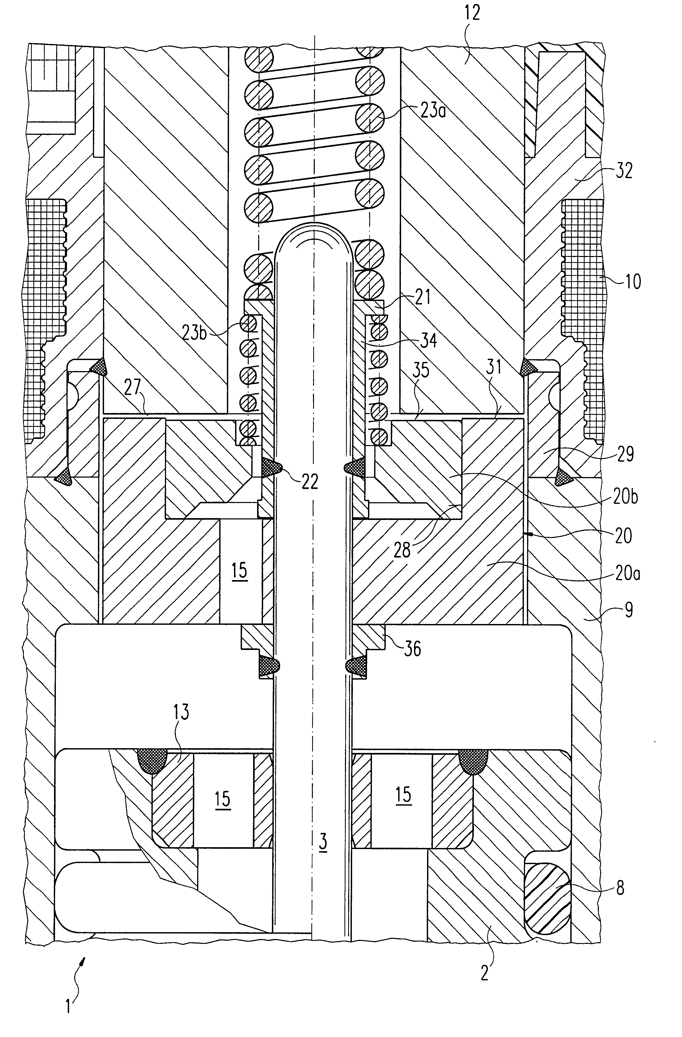
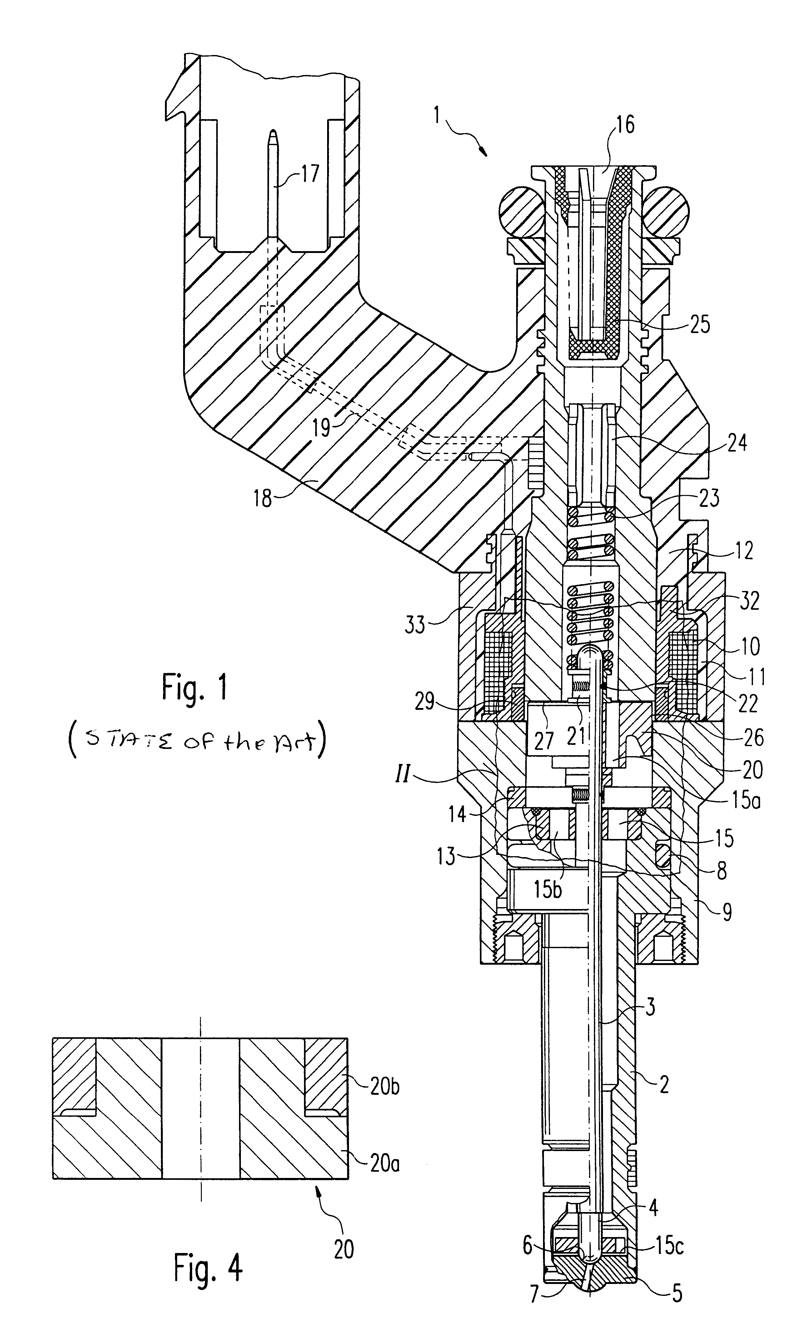
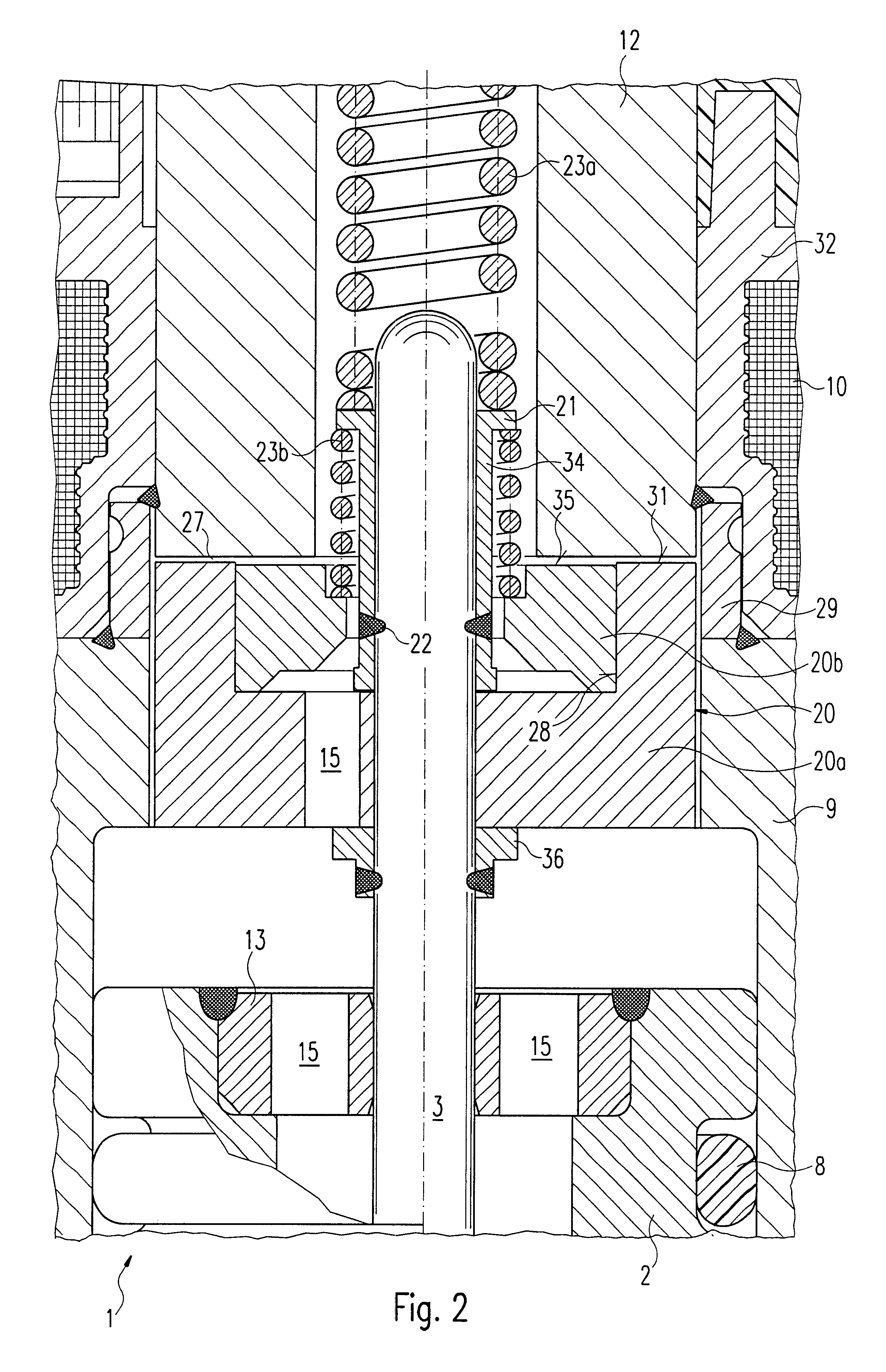
Before the three exemplary embodiments of a fuel injector according to the present invention are described in greater detail on the basis of FIGS. 2 through 4, an already known fuel injector will first be briefly discussed on the basis of FIG. 1 for the purpose of better comprehension of the present invention with respect to its essential components.

Fuel injector 1 is executed in the form of an injector for fuel injection systems of mixture-compressing, spark-ignition internal combustion engines. Fuel injector 1 is especially well suited for the direct injection of fuel into an undepicted combustion chamber of an internal combustion engine.

Fuel injector 1 is made up of a nozzle body 2, in which a valve needle 3 is guided. Valve needle 3 stands in an operative connection to a valve-closure member 4, which cooperates with a valve seat surface 6 arranged on a valve seat body 5, forming a sealing seat. Fuel injector 1 in the exemplary embodiment is a fuel injector 1 that opens to the in...


PUM


Abstract

A fuel injector (1) for fuel injection systems of internal combustion engines is specially designed for the direct injection of fuel into the combustion chamber of an internal combustion engine. It is provided with a solenoid coil (10), a two-part armature (20a, 20b) that is acted upon through the solenoid coil (10) in a closing direction by a first resetting spring (23a), and a valve needle (3) that is connected to the larger armature part (20a) in a force-locking manner, for actuating a valve-closure member (4) which together with a valve seat surface (6) forms a sealing seat. The first armature part (20a) is acted upon in the closing direction by the first resetting spring (23a), and the second armature part (20b) is acted upon in the closing direction by the second resetting spring (23b), the spring constants of the resetting springs (23a, 23b) being different.

Description

BACKGROUND INFORMATIONThe present invention relates to a fuel injector according to the species of the main claim.From German Patent 33 14 899 A1, an electromagnetically actuatable fuel injector is already known, in which, for the electromagnetic actuation, an armature cooperates with an electrically excitable solenoid coil, and the stroke of the armature is transmitted to a valve-closure member via a valve needle. The valve-closure member cooperates with a valve seat surface to form a sealing seat. The armature is not fixedly mounted on the valve needle, but is arranged thereon so as to be axially movable. A first resetting spring acts upon the valve needle in the closing direction and thus holds the fuel injector closed in the currentless, non-excited state of the solenoid coil. The armature is acted upon by a second resetting spring in the stroke direction such that the armature in the neutral position contacts a first limit stop provided on the valve needle. When the solenoid co...

Claims


Application Information

Patent Timeline
Patent Type & Authority Patents(United States)
IPC IPC(8): F02M51/06F02M61/10
CPCF02M51/0625F02M51/0685F02M51/0671F02M51/0664
Inventor STIER, HUBERT
Owner ROBERT BOSCH GMBH
Why Eureka
Try Eureka