Gas turbine engine

a technology of gas turbine engine and turbine blade, which is applied in the direction of engine starter, turbine/propulsion engine ignition, turbine/propulsion fuel heating, etc., can solve the problems of fuel loss of the required properties, reduced engine efficiency, and limited useable cooling capacity of hydrocarbon fuel

Active Publication Date: 2014-04-03
ROLLS ROYCE PLC
View PDF13 Cites 22 Cited by
  • Summary
  • Abstract
  • Description
  • Claims
  • Application Information

AI Technical Summary

Benefits of technology

[0029]The method may comprise controlling the valve in response to a measurement of any of fuel flow rate through the fuel passage, fuel temperature in the fuel passage relative to a critical temperature of the fuel in the fuel line. The method may comprise reducing the engine cooling air flow where the fuel flow falls below a first predetermined value, and increasing the engine cooling air flow where the fuel flow rises above a second predetermined value.
[0030]The method may comprise controlling the valve in response to the temperature of the fuel flowing through the fuel line in use. The method may comprise increasing the engine cooling air flow where the fuel temperature falls below a first predetermined value, and reducing the engine cooling air flow where the fuel flow rises above a second predetermined value. The second predetermined value may be related to the critical temperature.

Problems solved by technology

As a result, more air is required to cool the turbines to a required temperature, resulting in reduced efficiency of the engine 10.
However, the useable cooling capacity of hydrocarbon fuel is limited by a “critical temperature” above which the fuel may lose its required properties.
In jet A1 hydrocarbon fuel having a dissolved oxygen level typical in aviation applications, coke may begin to form in fuel that is heated to a temperature above 150° C. Coke deposits can cause degradation of fuel delivery performance by blocking or partially blocking fuel lines and / or injectors.

Method used


Image

  • Gas turbine engine
  • Gas turbine engine
  • Gas turbine engine

Examples


Embodiment Construction

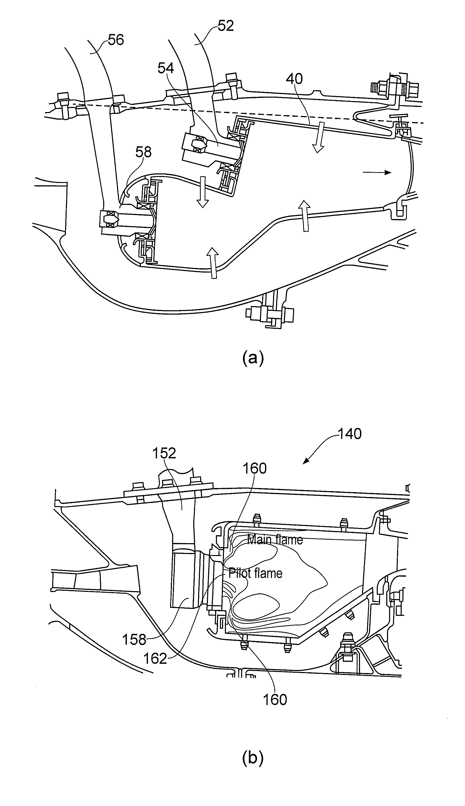
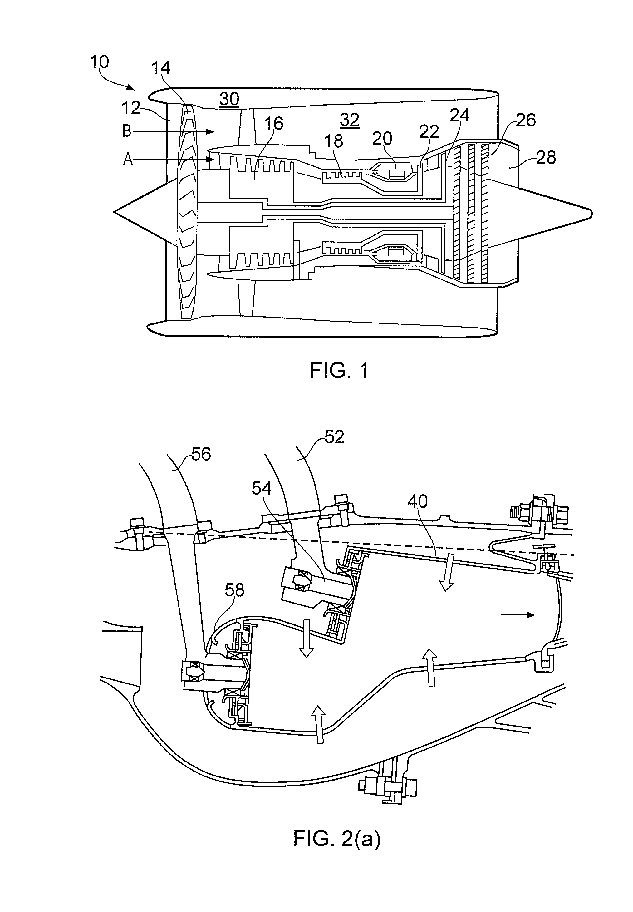
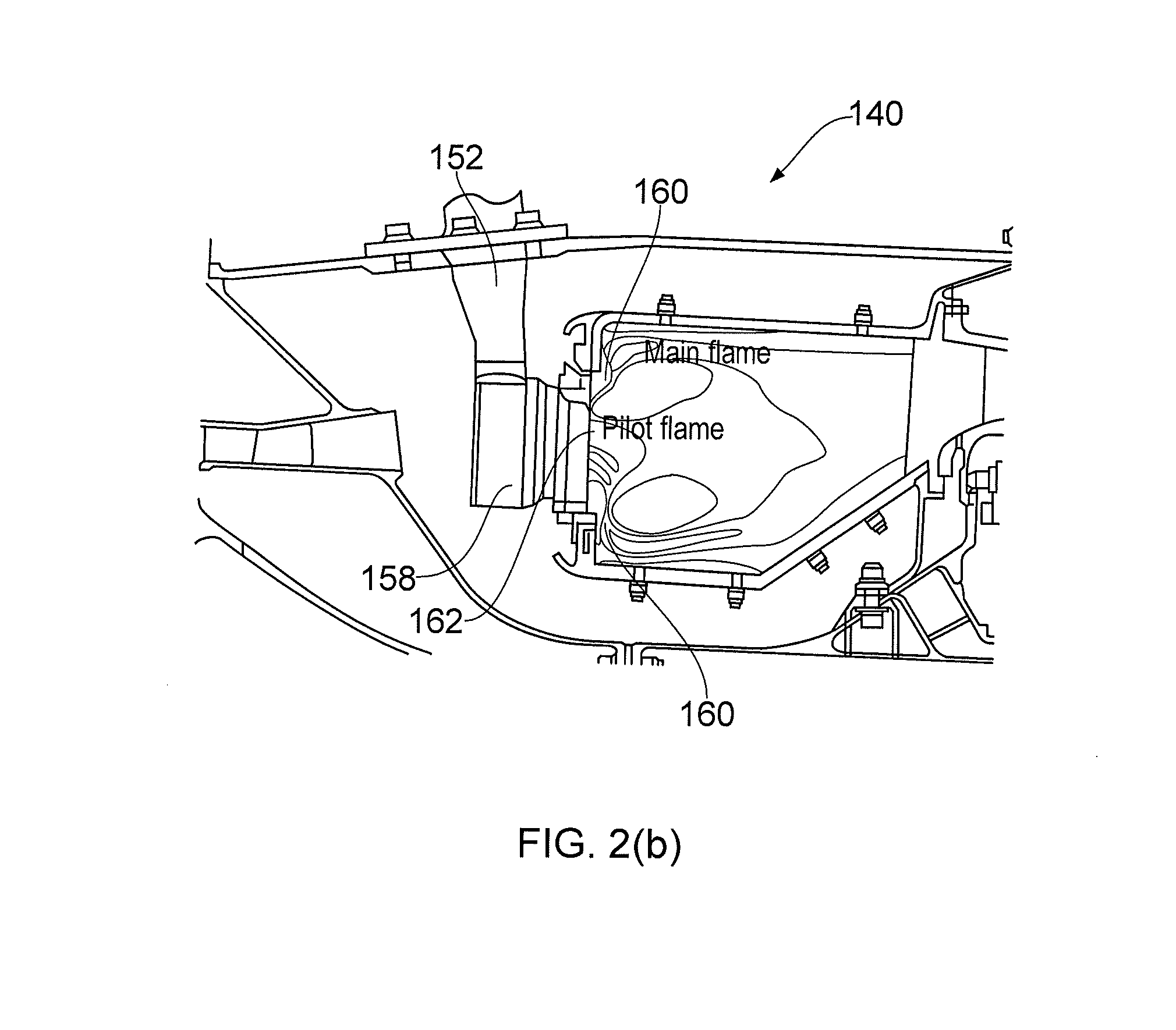
[0039]FIG. 1 shows a gas turbine engine 10. The gas turbine engine 10 generates heat in the combustor 20 by burning fuel with air provided by the fan 14 and the compressor 16, 18. This heat is transmitted to engine fluids such as fuel, oil and air, and is managed by a cooling system 60, shown schematically in FIG. 3.

[0040]The cooling system 60 includes a fuel tank 62 which contains a liquid fuel. Examples of typical liquid fuels include hydrocarbon based fuels such as kerosene, jet A1 and diesel. Fuel stored in the fuel tank 62 will also generally contain impurities such as dissolved oxygen.

[0041]The fuel is first pumped by a low pressure fuel pump 64 through a fuel line 66 to an engine fuel oil heat exchanger 68. The fuel line 66 passes through a fuel oil heat exchanger 68. The fuel oil heat exchanger 68 includes a heat exchange matrix comprising fuel and oil passages. Hot oil from the engine 10 is supplied through an oil line 70 through the fuel oil heat exchanger 68. The heat fro...


PUM


Abstract

A cooling system for a gas turbine engine (10). The system is comprises a fuel air heat exchanger (78) comprising a fuel passage (80) in thermal contact with an engine cooling air passage (82). The system further comprises a fuel deoxygenator (72) located upstream of the fuel air heat exchanger (78) configured to deliver deoxygenated fuel to the fuel air heat exchanger fuel passage (80). The system includes a valve (84) configured to moderate engine cooling air flow to the engine cooling air passage (82).

Description

[0001]The present invention relates to a gas turbine engine, and in particular the invention relates to a gas turbine engine having a fuel air heat exchanger to provide cooled air to an engine component, and a method of moderating cooled air provided to the engine component.BACKGROUND TO THE INVENTION[0002]A gas turbine engine 10 is shown in FIG. 1 and comprises an air intake 12 and a propulsive fan 14 that generates two airflows A and B. The gas turbine engine 10 comprises, in axial flow A, an intermediate pressure compressor 16, a high pressure compressor 18, a combustor 20, a high pressure turbine 22, nozzle guide vanes 23, an intermediate pressure turbine 24, a low pressure turbine 26 and an exhaust nozzle 28. A nacelle 30 surrounds the gas turbine engine 10 and defines, in axial flow B, a bypass duct 32.[0003]As well as flowing directly to the combustor 20 for combustion with fuel, a portion of the air flow A flowing through intermediate and high pressure compressors 16, 18 is ...

Claims


Application Information

Patent Timeline
Patent Type & Authority Applications(United States)
IPC IPC(8): F02C7/141
CPCF02C7/141F02C7/185F02C7/224F05D2260/213F05D2270/303Y02T50/60
Inventor APPUKUTTAN, AJITHROLT, ANDREW MARTINMORAN, ANTHONY JOHN
Owner ROLLS ROYCE PLC
Why Eureka
Try Eureka