Device and method for wet treating disc-shaped articles

a technology of disc-shaped objects and wet treatment, which is applied in the manufacture of semiconductor/solid-state devices, basic electric elements, electrical equipment, etc., can solve the problems of high liquid consumption, high afford for cleaning the exhausted air, and increase the process cost, so as to reduce the exhaust volume, avoid cross-contamination between two neighbouring collector levels, and reduce the effect of gas flow

Active Publication Date: 2010-11-23
LAM RES AG
View PDF17 Cites 38 Cited by
  • Summary
  • Abstract
  • Description
  • Claims
  • Application Information

AI Technical Summary

Benefits of technology

[0022]An advantage of the invention is that a significant reduction of the exhausted volume is possible and that cross-contamination between two neighboured collector levels can be avoided.
[0023]Optionally the device has exhaust influencing means, which are flow control modulating valve, such as a butterfly valve. This allows not only to shut off an exhaust level, but also to precisely lower gas flow in every exhaust level.
[0024]In an advantageous device the at least one exhaust influencing means is a closing valve, whereby one of the at least two exhaust levels can be closed. Such a configuration allows an easier control.
[0025]In another embodiment the device comprises controlling means whereby the at least one exhaust influencing means is controlled in dependence of the relative position of spin-chuck to liquid collector. Although this can be carried out easily in a mechanic way by connecting exhaust influencing means direct with the lifting means this will typically be done by a computer. In the latter case the computer receives information about the relative position of chuck to liquid collector either directly from the lifting means or electronic detectors detect the position.
[0026]If the suction orifices of at least one of the exhaust levels are connected to one of the two collector levels this collector level at the same time serves as exhaust level. The gas is sucked from the interior of the liquid collector into the collector level and therein separated from the liquid.
[0027]Yet another embodiment has at least one of the at least two exhaust levels arranged above or below of a collector level. In this case the collector level only collects liquid and does not suck gas as well. This brings the advantage that gas and liquid do not have to be separated after being collected.

Problems solved by technology

This is not only because a high exhaust volume per time unit raises process cost, but also because too high exhaust sucks too much liquid into the exhaust, which has the disadvantages of high liquid consumption and of high afford for cleaning the exhausted air.

Method used


Image

  • Device and method for wet treating disc-shaped articles
  • Device and method for wet treating disc-shaped articles
  • Device and method for wet treating disc-shaped articles

Examples


Embodiment Construction

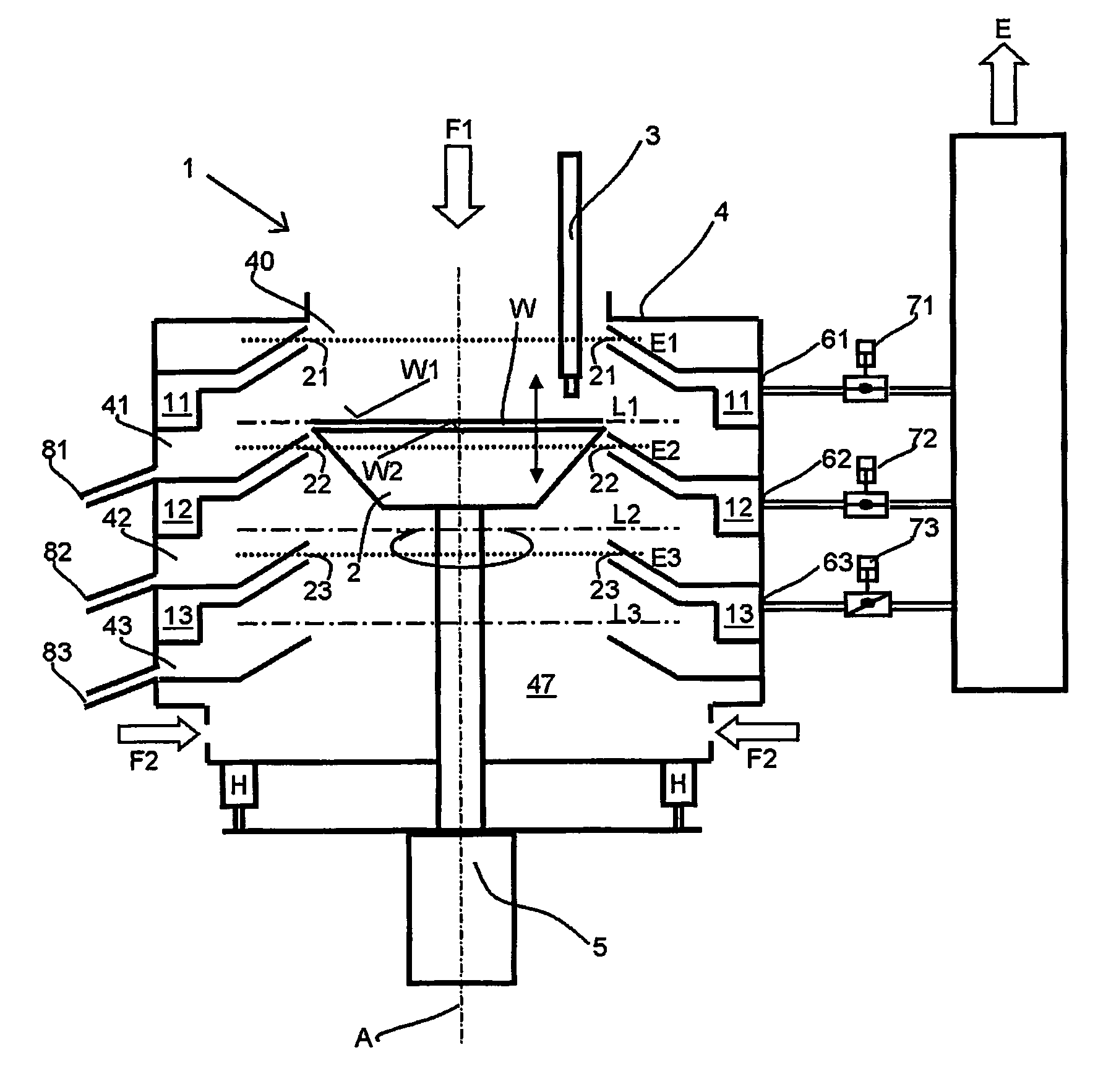
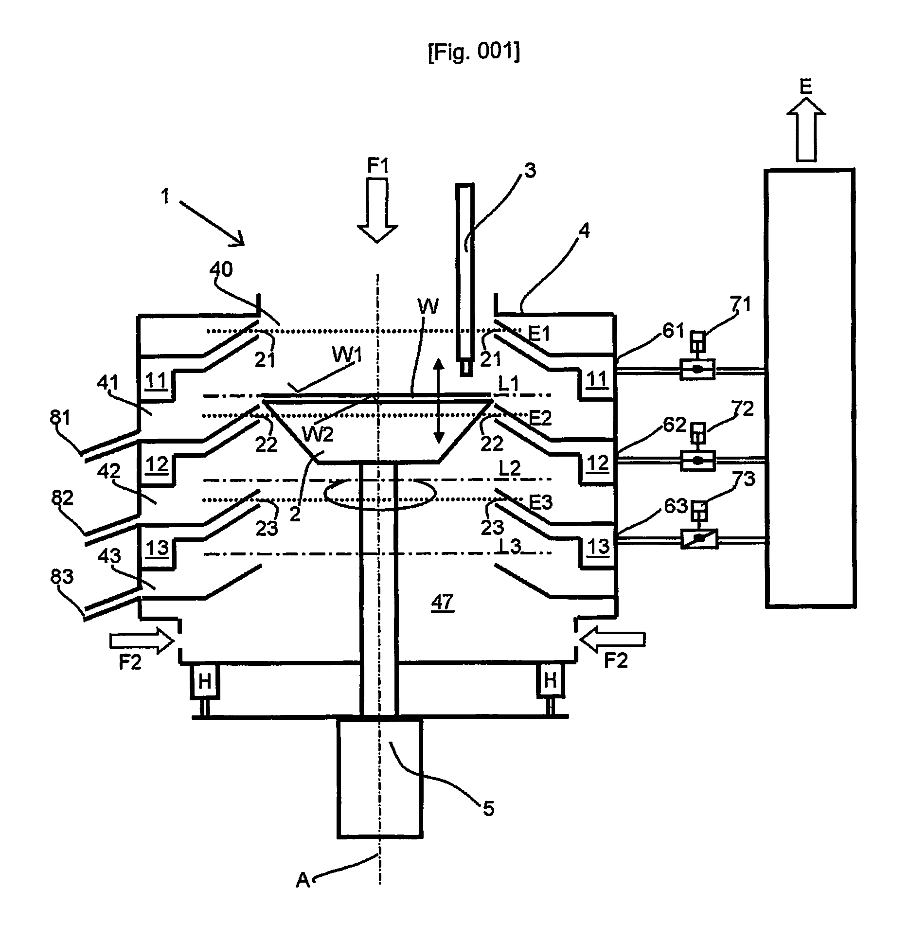
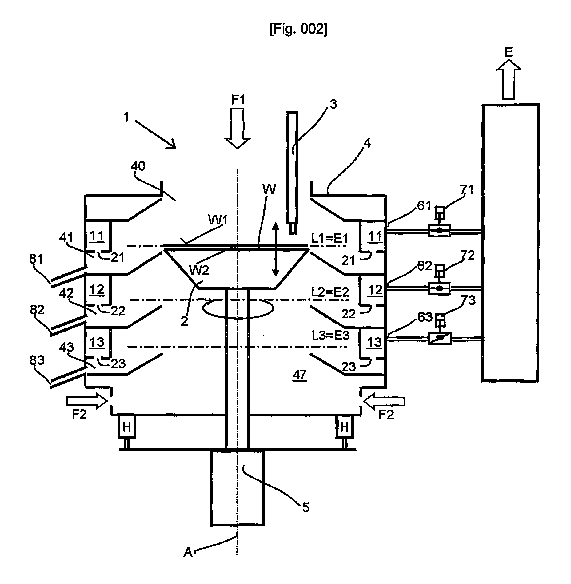
[0034]A cup-like liquid collector 4 circumferentially surrounds the spin-chuck 2. The liquid collector is mounted on a frame (not shown). Lifting means H are provided to alter the spin-chuck position relative to the liquid collector. Thus the spin-chuck can be lifted to each of the three collector levels L1, L2 and L3. Each collector level L1, L2, L3 comprises an annular duct 41, 42, 43 to have spun off liquid collected therein. An additional splash guard (not shown) can be used for each collector to allow spun off liquid to hit it at an acute angle and thereafter to be directed to the annular duct. Each annular duct 41, 42, 43 is connected to a pipe 81, 82, 83 through which the collected liquid is drained. Drained liquid can immediately be reused to be dispensed to the substrate or collected as waste liquid. Each collector level L1, L2, L3 is for collecting different liquids. L1 is for collecting rinse liquid (e.g. DI-water), L2 for acidic liquids and L3 for basic liquids.

[0035]The...


PUM


Abstract

In a spin-chuck with plural collector levels, a separate exhaust controller is provided for each level. This permits selectively varying gas flow conditions among the collector levels, so that the ambient pressure at one level does not adversely affect device performance in an adjacent level.

Description

BACKGROUND OF THE INVENTION[0001]1. Field of the Invention[0002]The invention relates to a device and a method for wet treating a flat plate-like substrate, such as semiconductor wafers, flat panel displays or compact discs. The device comprising a spin-chuck for holding and rotating the substrate, at least one dispenser for dispensing a liquid onto at least one surface of said substrate, a liquid collector circumferentially surrounding said spin-chuck for collecting liquid, which is spun off the substrate during rotation. The liquid collector has at least two collector levels. Each of the collector levels has the purpose of separately collecting liquids in different collectors.[0003]The device further comprises lifting means for moving spin-chuck relative to liquid collector substantially along the rotation axis and at least two exhaust levels for separately collecting gas from the interior of the liquid collector. Collecting gas from the interior of the liquid collector is useful ...

Claims


Application Information

Patent Timeline
Patent Type & Authority Patents(United States)
IPC IPC(8): B08B5/00H01L21/00
CPCH01L21/67051H01L21/6708Y10S134/902H01L21/304H01L21/302
Inventor HOHENWARTER, KARL-HEINZ
Owner LAM RES AG
Why Eureka
Try Eureka