Eureka AIR delivers breakthrough ideas for toughest innovation challenges, trusted by R&D personnel around the world.

Airflow assisted ramp loading and unloading of sliders in hard disk drives

a technology of hard disk drives and ramps, which is applied in the direction of maintaining head carrier alignment, recording information storage, instruments, etc., can solve the problem that the air flow emerging through the first openings is not sufficient to hold the tab completely

Inactive Publication Date: 2005-02-15
WESTERN DIGITAL TECH INC
View PDF6 Cites 38 Cited by
  • Summary
  • Abstract
  • Description
  • Claims
  • Application Information

AI Technical Summary

Benefits of technology

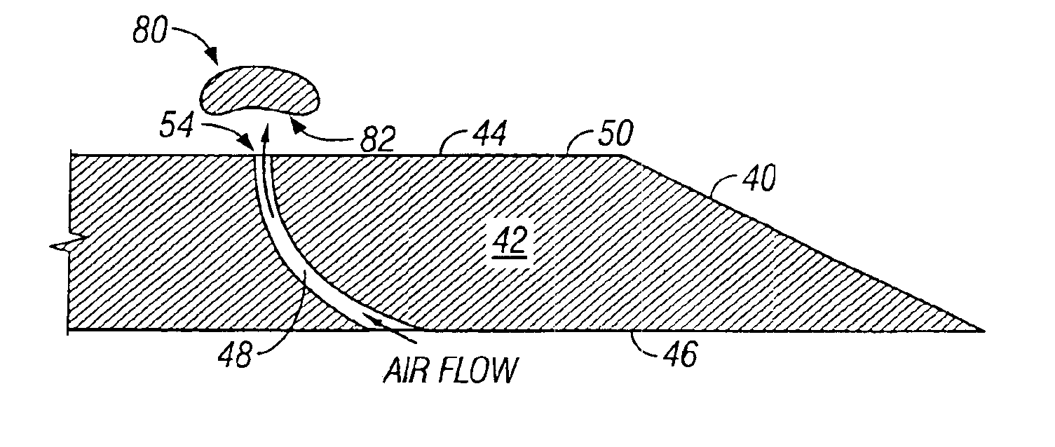
The present invention provides for a ramp to assist the loading and unloading of a slider in a magnetic disk drive. The ramp comprises a body having a first surface and a second surface and a plurality of apertures extending between them, where each aperture has a first opening at the first surface and a second opening at the second surface. The first surface of the ramp further comprises a sloped segment and a straight segment, with the sloped segment being acutely angled with respect to the second surface. The ramp of the present invention directs a portion of a flow of air proximate to a spinning disk through the apertures in order to lift and cushion a tab attached to a load beam from which a slider is also suspended.
The method of unloading the slider further includes flying the slider over the disk, pivoting the load beam such that the tab engages a sloped segment of the ramp as the load beam is pivoted to an outside diameter of the disk, moving the tab over the sloped segment and onto the straight segment of the ramp, and reducing the rotation of the disk to reduce the flow of air through the apertures to allow the tab to be supported on the straight segment of the ramp. Further embodiments of both methods include supporting the tab on an air bearing while it is moving relative to the ramp. Other embodiments of both methods are directed to providing an amount of lift to the tab that is not sufficient to raise the tab off of the ramp, but is sufficient to lower the contact force between the tab and the ramp.

Problems solved by technology

In other embodiments the air flow emerging through the first openings is not sufficient to hold the tab completely off of the surface of the ramp.

Method used


Image

  • Airflow assisted ramp loading and unloading of sliders in hard disk drives
  • Airflow assisted ramp loading and unloading of sliders in hard disk drives
  • Airflow assisted ramp loading and unloading of sliders in hard disk drives

Examples


Embodiment Construction

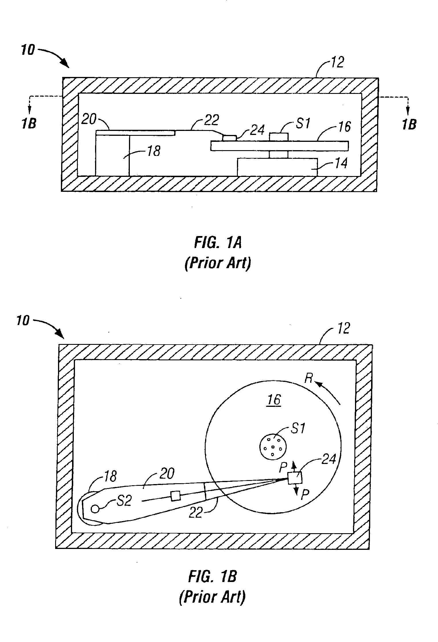
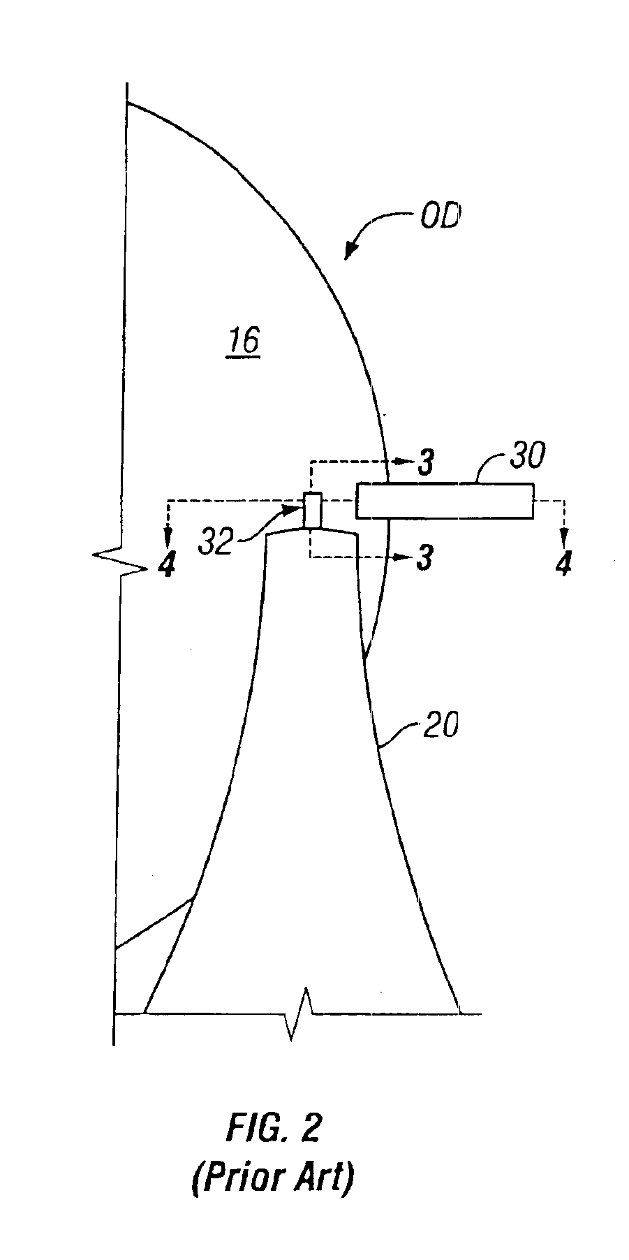
FIGS. 1A, 1B, and 2-4 were discussed above with reference to the prior art.

FIG. 5 shows a perspective view of the ramp 40 of the present invention. The ramp 40 comprises a body 42 having a first surface 44 and a second surface 46 and a plurality of apertures 48 extending between the two. The body 42 is preferably formed of a plastic, such as Teflon, or plastic-like material selected for having very low levels of outgassing of volatile organic compounds and very low levels of particle shedding. The body 42 should also be formed of a material that is resistant to wear and that can be readily machined or otherwise formed. In some embodiments ceramic materials or metallic materials can be used to form the body 42. Further embodiments include surface treatments, lubricants, and specially formed solid surface layers to provide additional wear resistance to first surface 44.

The first surface 44 is further divided into two sections, a straight segment 50 and a sloped segment 52, the sloped ...


PUM

PropertyMeasurementUnit
diameteraaaaaaaaaa
aerodynamic shapeaaaaaaaaaa
cross-sectional areasaaaaaaaaaa

Abstract

Windage proximate to a spinning disk within a disk drive is directed through a plurality of apertures in a ramp situated near the outside diameter of the disk. A tab extending from a load beam that supports a slider rests on the ramp when the drive is not in use. When the drive is started the disk begins to spin and an actuator moves the load beam to bring the slider over the surface of the disk. As the load beam moves, the tab is guided along the ramp and cushioned by the air flow emerging from apertures in the ramp beneath it. When the drive is stopped the actuator brings the load beam back so that the tab engages the ramp. A cushion of air is again provided as the tab is moved along the ramp as the tab is returned to a parked position.

Description

BACKGROUND OF THE INVENTIONThis invention relates generally to magnetic disk data storage systems, and more particularly to the use of a ramp to facilitate the loading and unloading of sliders.Magnetic disk drives are used to store and retrieve data for digital electronic apparatuses such as computers. In FIGS. 1A and 1B, a magnetic disk data storage system 10 of the prior art includes a sealed enclosure or housing 12, a spindle motor 14, a magnetic medium or disk 16, supported for rotation by a drive spindle S1 of the spindle motor 14, a voice-coil actuator 18 and a load beam 20 attached to an actuator spindle S2 of voice-coil actuator 18. A slider support system consists of a flexure 22 coupled at one end to the load beam 20, and at its other end to a slider 24. The slider 24, also commonly referred to as a head or a read / write head, typically includes an inductive write element with a sensor read element.As the motor 14 rotates the magnetic disk 16, as indicated by the arrow R, a...

Claims


Application Information

Patent Timeline
Patent Type & Authority Patents(United States)
IPC IPC(8): G11B21/22G11B21/12G11B5/54G11B21/21
CPCG11B5/54G11B21/22G11B21/12
Inventor HAWWA, MUHAMMAD A.BOZORGI, JAMSHIDMENON, ARIC
Owner WESTERN DIGITAL TECH INC
Why Eureka
Eureka Blog
Learn More