Friction plate and wet-type multi-plate clutch

a multi-plate clutch, friction plate technology, applied in the direction of fluid-actuated clutches, clutches, non-mechanical actuated clutches, etc., can solve the problems of insufficient drag torque reduction, inability to meet the request for further reducing drag torque, and severely limited grooves to be formed in the friction plate, so as to reduce the shock caused by engagement, reduce the number of grooves to be formed, and reduce the drag torque during idle rotation.

Inactive Publication Date: 2007-05-10
NSK WARNER
View PDF22 Cites 39 Cited by
  • Summary
  • Abstract
  • Description
  • Claims
  • Application Information

AI Technical Summary

Benefits of technology

[0011] Accordingly, an object of the present invention is to provide a friction plate which has good heat resistance and in which shock caused upon engagement is reduced and drag torque during an idle rotation can be greatly reduced in comparison with conventional cases, and a wet-type multi-plate clutch having such a friction plate.
[0013] According to the present invention, the following effects can be obtained:
[0014] Since the oil groove opened only to the outer diameter side is provided in the surface of the friction material, oil drawn from the oil passage to the friction surface can be discharged smoothly toward the outer diameter side, with the result that the drag torque can be reduced in the idle rotation. Particularly, during a low rotation, the drag torque can be reduced considerably. Further, since the drawn oil can be removed smoothly, friction heat generated during engagement can also be removed smoothly together with the oil, thereby enhancing heat resistance of the friction material.
[0016] Further, the oil groove opened to the inner diameter side and having the closed end portion has a function for maintaining the clearance between the friction plate and the separator plate constant during the idle rotation by an action for separating the friction plate and the separator plate from each other and a function for disengaging the clutch smoothly during the releasing of the clutch and a cushion function for preventing abrupt abutment of the clutch in the initial engagement.
[0017] Further, when the width of the oil passage is smaller at the outer diameter side than at the inner diameter side, a more amount of oil can be supplied to the friction surface, whereas, conversely, when the width is greater at the outer diameter side, an amount of oil discharged from the oil passage is increased.
[0018] Various designs can be adopted on the basis of oil supplying amounts and rotating conditions used. Similarly, when a width of the oil groove opened to the inner diameter side is greater at the inner diameter side, the effect for separating the friction material can be more enhanced. Incidentally, when both of the oil passage and the oil grooves are formed in an inclined manner with respect to a radial direction, the oil discharging ability of the friction surface is more enhanced.

Problems solved by technology

In conventional friction plates, since the lubricating oil on the friction surface is not discharged adequately, a request for further reducing the drag torque could not be satisfied.
In particular, during a low rotation, since the oil interposed between the friction plate and the separator plate was not discharged adequately, the drag torque could not be reduced.
To this end, the number of grooves to be formed in the friction plate, as well as the dimension of each groove, has been limited severely.

Method used


Image

  • Friction plate and wet-type multi-plate clutch
  • Friction plate and wet-type multi-plate clutch
  • Friction plate and wet-type multi-plate clutch

Examples


first embodiment

(First Embodiment)

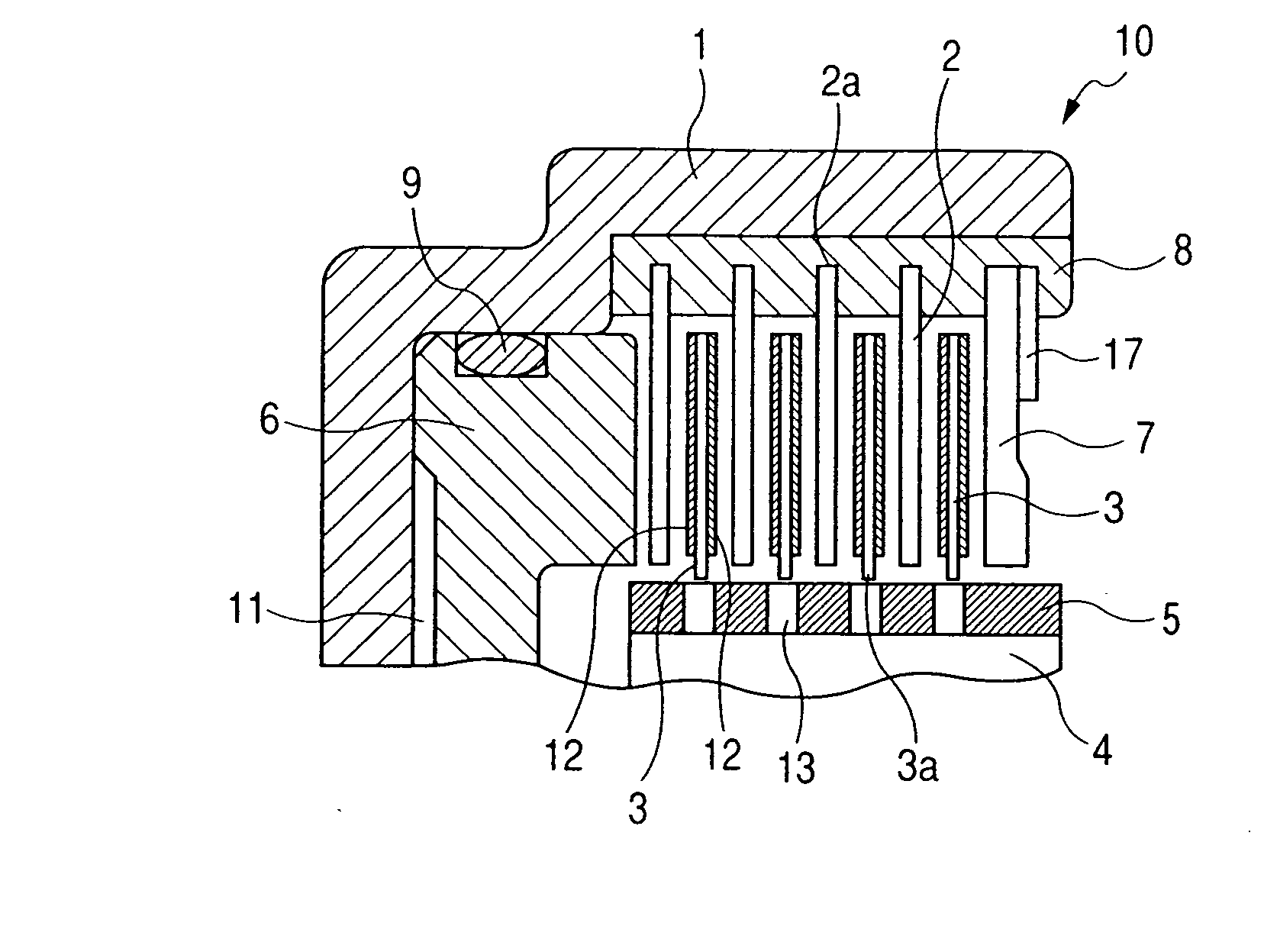
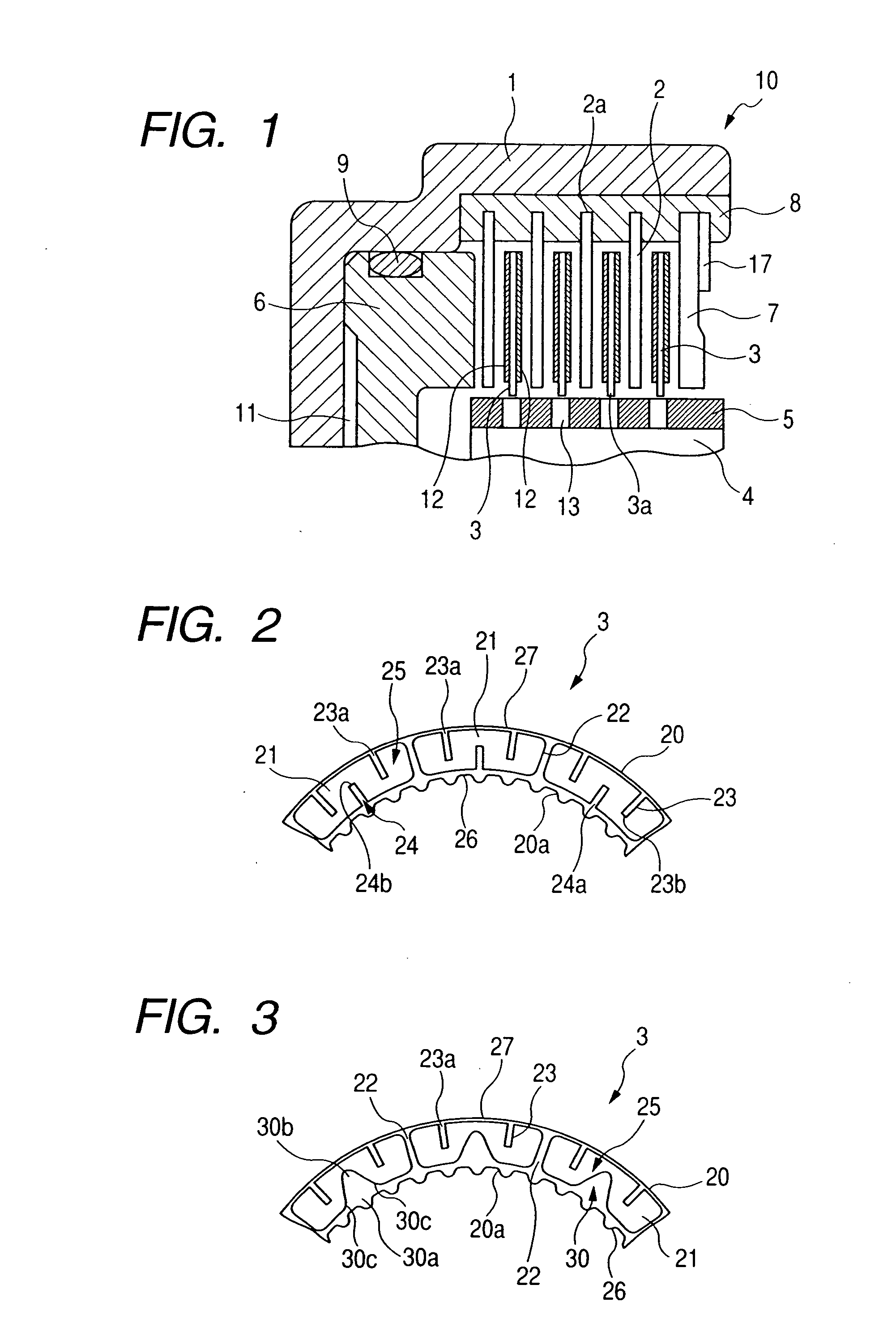
[0044]FIG. 2 is a partial front view of a friction plate 3 according to a first embodiment of the present invention. The friction plate 3 has a friction surface 25 obtained by adhering a plurality of friction material segments 21 to a substantially annular core plate 20 by an adhesive. The core plate 20 is provided with at its inner periphery with splines 20a for engaging with splines 5 of the hub 4.

[0045] As shown, each friction material segment 21 is provided with a first oil groove 24 having an opening portion 24a opened to an inner peripheral edge 26 of the friction plate 3 and an end portion 24b terminating at a position between inner and outer peripheral edges, and second oil grooves 23 each having an opening portion 23a opened to an outer peripheral edge 27 of the friction plate 3 and an end portion 23b terminating at a position between the inner and outer peripheral edges. In each segment, a single first oil groove 24 is provided and two second oil grooves...

second embodiment

(Second Embodiment)

[0049]FIG. 3 is a partial front view of a friction plate 3 according to a second embodiment of the present invention. A fundamental construction of the second embodiment is the same as that of the first embodiment. Accordingly, only a difference will be described. Also in third to thirteenth embodiments which will be described later, only differences will be described.

[0050] In the second embodiment, a first oil groove 30 having an opening portion 30a opened to the inner peripheral edge 26 of the friction plate 3 and an end portion 30b terminating at a position between inner and outer peripheral edges is provided in each segment. As shown, the first oil groove 30 has a tapered portion 30c extending from both circumferential ends of the opening portion 30a to the end portion 30b. Accordingly, the first oil groove 30 is tapered so that a circumferential width of the oil groove is gradually increased from the end portion 30b to the opening portion 30a.

third embodiment

(Third Embodiment)

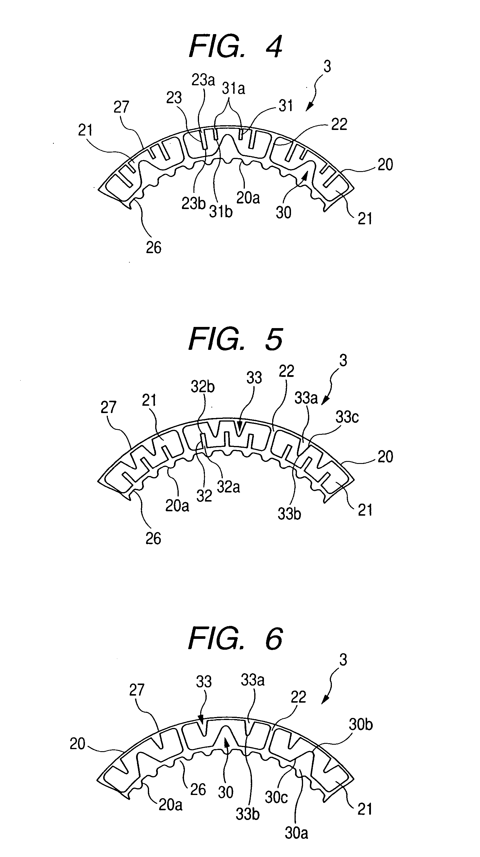
[0051]FIG. 4 is a partial front view of a friction plate 3 according to a third embodiment of the present invention. A fundamental construction of the third embodiment is the same as that of the first embodiment. Accordingly, only a difference will be described.

[0052] The third embodiment is an alteration of the second embodiment, in which constructions of a first oil groove 30 and second oil grooves 23 are substantially the same as those in the second embodiment. In the third embodiment, a difference is that third oil grooves 31 are provided in each segment. Each of the third oil grooves 31 has an opening portion 31a at the outer peripheral edge 27 and an end portion 31b terminating at a position between the inner and outer peripheral edges.

[0053] Each third oil groove 31 is disposed between the first oil groove 30 and the second oil groove 23 and a radial length of the third oil groove is shorter than a length of the second oil groove 23. Further, a circumferen...


PUM


Abstract

The present invention provides a friction plate having a friction surface formed by adhering a friction material to a substantially annular core plate and wherein the friction surface is provided with an oil passage communicated with inner and outer peripheral edges of the friction plate, a first oil groove having an opening portion opened to the inner peripheral edge of the friction plate and an end portion terminating at a position between the inner and outer peripheral edges, and a second first oil groove having an opening portion opened to the outer peripheral edge of the friction plate and an end portion terminating at a position between the inner and outer peripheral edges.

Description

BACKGROUND OF THE INVENTION [0001] 1. Field of the Invention [0002] The present invention relates to a friction plate used in a clutch or a brake of an automatic transmission (AT) of a vehicle, and, a wet-type multi-plate clutch having such a friction plate. More specifically, the present invention relates to an improvement in an oil passage formed in a friction surface of the friction plate. [0003] 2. Related Background Art [0004] Generally, in a wet-type multi-plate clutch, friction plates and separator plates are alternately arranged between a drum and a hub of a clutch or a brake, so that engagement and disengagement of the clutch are performed by urging and releasing of a clutch piston. [0005] Further, in recent years, request for reduction of fuel consumption in a vehicle has been increased more and more, and, in also an automatic transmission, in order to reduce power loss during disengagement of the clutch, reduction in drag torque between the friction plate and the separato...

Claims


Application Information

Patent Timeline
Patent Type & Authority Applications(United States)
IPC IPC(8): F16D13/00
CPCF16D13/648F16D2069/004F16D25/0638F16D25/123
Inventor MIYAZAKI, TOMOYUKITOYA, RITSUOHIRAYANAGI, TSUYOSHIKOBAYASHI, MASAHIRO
Owner NSK WARNER
Why Eureka
Try Eureka